Continuous Wave (CW) radars emit a very high frequency signal continuously. The echo signal is received and processed, and the receiver (which has its own receiving antenna) is arranged in the same place as the transmitter. Any civil radio transmitter can be used as a radar transmitter if a receiver located at a distance from the transmitter is used, which compares the propagation time of the direct signal with the propagation time of the reflected signal.
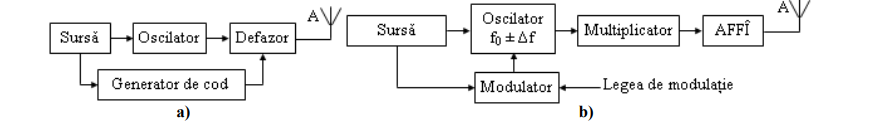
-Radars with continuous transmission without modulation
The emission signal of these radars is constant in amplitude and frequency. This type of radars are specialized in determining the speed. Distance cannot be measured. For example, they are used by the police to measure the speed of motor vehicles (radar speedometers). More modern equipment (LIDAR) works in the range of laser frequencies and can do out-of-speed and other measurements.
-Continuous emission radars with modulation
The emission signal is constant in amplitude but modulated in frequency. This modulation again makes possible the principle of measuring the propagation time. Another advantage of these radars is that the reception of signals is done without interruptions and so the measurement results are available continuously. These radars are used to determine not very long distances when a continuous measurement is required
A similar principle is used by impulse radars whose pulses have long durations, thus affecting the ability to separate in distance. These radars use an internal modulation of the emitted pulses, thus making it possible to improve the distance resolution by the pulse compression method
GENERAL BLOCK SCHEME. ROLE OF THE ELEMENTS
Two types of transceiver installations are possible, namely, with a single antenna,
respectively with separate antennas for transmission and reception. Their block schemes are
shown in Figure 1.1.
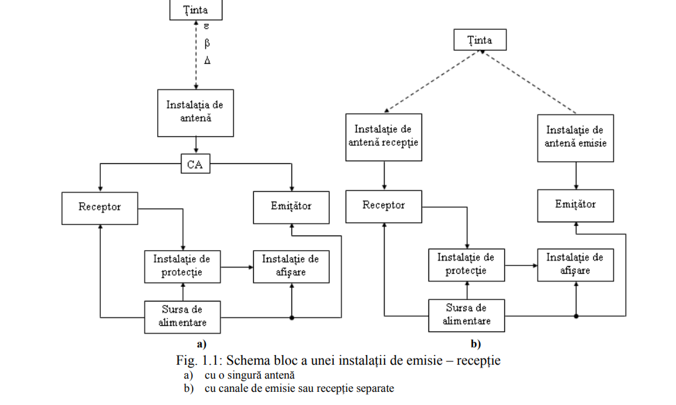
CA – antenna switch; ensures the separation in time of the reception broadcast. It follows that the scheme
with CA cannot be used in continuous emission systems.
ROLE OF THE ELEMENTS
The emitter has the role of emitting elecromagnetic radiation with the parameters imposed by construction, the most important being the following:
Radiation type: Continuous:
• Unmodulated.
• Modulated in amplitude, frequency or phase (MA, MF, MΦ ).
In momentum:
• With constant or variable emission frequency (less often);
• With constant or variable repetition frequency (vobulation);
• With or without code.
Power:
Instantaneous (energy with continuous variation): Pi = Pmedie ;
In impulse (energy with pulse variation): Pmedie < Pimpuls .
The law of modulation, in the case of transmitting modulated signals:
In the case of continuous emission, the most changed are MA, MF;
In the case of pulse emission, the most used are position modulation
and modulation in code.
Number of channels:
With a single transmitter;
Multichannel:
• With spatial separation;
• With separation in time (less often used),
• With time and spatial separation.
Emission frequency:
Constant (with or without re-agreement);
With frequency jumps in a certain spread.
- The receiver has the role of processing the received signal in order to bring it to the form required for display. The processing performed can be the following:
- Direct amplification via Highly Frequency Amplifiers
High (AFFÎ), which however are characterized by a small amplification (they work on
high frequency, so they have wide passing bandwidth and small amplification); - Approximate selection of useful signal between noises (preselector, circuits of
entry granted); - Translation to lower frequencies in order to be subsequently strongly amplified (Frequency Exchangers - SF);
- Basic amplification, in average frequency (Intermediate Frequency Amplifier - AFI);
- Detection (transposition into video or audio signal):
- Selection of the useful signal
Preparation of the selected signal for transmission to the display installation (repeater for adaptation to the transmission line, digitization, etc.)
- The display installation must display in a desired form the signal useful for the operator.
- The power supply provides the necessary energy for the operation of the transceiver installation
It may include:
- Generator group, which may be missing if there is power supply from the network;
- Frequency converters (e.g. 50Hz to 400Hz);
- Rectifiers;
- Voltage stabilizers (for continuous voltages with low tolerances)
Voltage riser transformers and high voltage rectifiers