Reading Activity
|
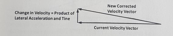
Once the guidance processor has determined the magnitude and direction of the error in the missile flight path and the autopilot has determined the steering command, the missile control system must adjust the control surfaces to produce the acceleration required to correct the flight path. This corrective acceleration is applied in a lateral direction (perpendicular to the missile flight path) to change the direction of the missile velocity vector (Figure 4). Intentional acceleration along the flight path to correct the magnitude of the velocity vector (for early or late arrival) is a potentially useful concept, but it is not presently used to guide surface-to-air missiles because of the complexity of throttling solid propellant motors.
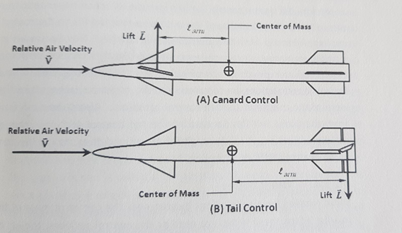
Fig. 4 Acceleration Required to Change Direction of Flight Canard Control Figure 7(A) shows how an aerodynamic moment is generated when the control surface is a canard fin (located at the front of the missile). With the canard fin rotated as shown, a lift L (similar to that on an airplane wing) is developed on the fin itself. This lift, acting on the lever larm relative to the missile center of mass, produces a nose-up moment when the fin is deflected as shown. The magnitude of the aerodynamic moment is proportional to the lift L that acts on the control surface. The lift in turn is dependent on the deflection angle of the control surface. Tail Control Figure 7(B) shows the use of tail surfaces for control. Either the entire tail fin is only the trailing edge is hinged as shown. With tail control the lift on the control surface is in the direction opposite to the desired lateral acceleration of the missile so that the lift on the control surface subtracts from the overall missile lift. This can result in slightly decreased lateral accelerations and slightly increased response time. Another disadvantage of tail control is that long electric and hydraulic connections are required from the guidance package near the nose of the missile to the tail control actuators. |
Fig. 7 Canard Control and Tail Control |