Definition
Meteorological radar is a radar that emits electromagnetic microwaves and uses their reflection on certain objects, such as clouds, to determine their position and distance from the radar antenna. Radar sends an impulse of electromagnetic energy into the atmosphere. If that energy interacts with something in the environment, it will reflect the energy back to the weather radar. Today, most radars use the Doppler effect and have dual polarization. A Doppler radar determines whether the movement is directed towards the radar or in the opposite direction. Dual polarization is a combination of radar design and software algorithms that help identify the type of precipitation.
Overview
The meteorological radar appeared after the Second World War, being originally used for military purposes.
One of the major factors that led to the spread of weather radars was the hurricane. In 1954, two hurricanes occurred along the East Coast of America within 11 days of each other. With two consecutive years of extensive damage, a budget was drawn up that included the implementation of additional radars. These were known as WSR-57. Until then there were WSR-1, WSR-1A, WSR-3 and WSR-4 radars, which had originally been used by Navy aircraft during World War II.
Conventional radars have been replaced by Doppler radars, which in addition to position and intensity can track the relative speed of particles in the air. The WSR-88D is the first radar of its kind, which not only detects an echo, but also determines its movement
Since 2000, research on dual polarisation technology has turned into operational use, increasing the amount of information available on the type of precipitation (e.g., rain and snow).
"Dual polarization" means that microwave radiation is emitted that is polarized both horizontally and vertically (relative to the ground). Doppler weather radar, using modern digital signal processing and display techniques, has advanced so much that the U.S. has replaced the existing operational weather radar network with a next generation doppler system (NEXRAD). This system will provide real-time quantitative and automated information about storms, precipitation, hurricanes, tornadoes, and a host of other important weather phenomena with a higher spatial and temporal resolution than before.
Principle of operation
The technical principle of meteorological radar is very similar to that of primary surveillance radar (PSR). There are a few major operating differences. This is often since the shape of the "object of interest" is considerably different (normally the weather is much more complex and fluid than moving targets), and the speed of the object is normally much lower than that of an aircraft. Meteorological targets are distributed in space and occupy a large fraction of the space resolution cells observed by radar. Further, it is necessary to carry out quantitative measurements of the characteristics of the received signal to estimate such parameters as the rate of precipitation, the type of precipitation, air movement, turbulence, and wind shearing. In addition, because so many cells with radar resolution contain useful information, weather radars require high-speed data recording systems and effective means of real-time display.
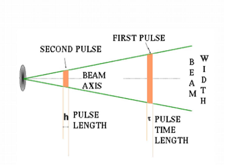
Weather radars send microwave-directed pulses, long on the order of microseconds.
Wavelengths of 1 to 10 cm are about ten times larger than the diameters of droplets or ice crystals of interest. The scattering of radiation at such frequencies is therefore rayleigh type. As a result, some of the energy of each pulse will be reflected by these particles, turning in the direction of the radar station.
Smaller wavelengths can detect smaller particles, but the signal is mitigated faster. Thus, the wavelength of 10 cm (S-band) is preferred, but it is more expensive than the X-band of 5 cm, and the meteorological radar in the L-band of 1 cm is used only for research on small particles such as drizzle or fog.
Radar pulses scatter as they move away from the radar station. This means that the region of air through which each given pulse moves increases as its position is further away from the station. It follows that the accuracy of the measurement decreases at greater distances. For example, at distances of 150-200 km, the volume of air scanned by a single pulse can be of the order of one cubic kilometer.
Variation of the refractive index with the altitude
The refractive index is a quantity that characterizes an interaction between light and matter, so it is intrinsically dependent on the characteristics of the environment and the incident electromagnetic wave. The index of an environment depends on the parameters that characterize the environment: temperature, pressure, density, etc. The constraints imposed on a transparent material also change its index.
Abnormal propagation- The first assumption is that the radar beam moves through air that cools down at a certain rate with height. The position of echoes largely depends on this assumption. However, the actual atmosphere can vary greatly from the norm.
Super refraction- Temperature inversions are often formed near the ground, for example by cooling the air at night, remaining warm upwards. As the air refractive index decreases faster than normal, the radar beam bends towards the ground instead of continuing upwards. Eventually, it will touch the ground and be reflected to the radar. The processing program will then wrongly place the return echoes at the height and distance that it would have been under normal conditions.
This type of false return is relatively easy to observe in a time loop if it is due to night cooling or marine reversal, it hurtsthat very strong echoes are seen developing over an area, spreading to the side, but without movement and varying greatly in intensity. However, the reversal of the temperature existing before the warm fronts and the abnormal echoes of propagation are then mixed with the actual rain.
The extreme of this problem is when the inversion is very strong and shallow, the radar beam is reflected several times towards the ground since it must follow a waveguide . This will create more bands of powerful echoes on the radar images.
Under refraction- On the other hand, if the air is unstable and cools faster than the standard atmosphere with height, the beam reaches higher than expected. This indicates that precipitation occurs higher than the actual height. Such an error is difficult to detect without additional data on the temperature rate for the zone.
Reflectivity (dBZ scale)
Reflectivity is the amount of transmitted power returned to the radar receiver. Reflectivity covers a wide range of signals (from very weak to very strong).
How do we read the reflectivity on the display of a radar?
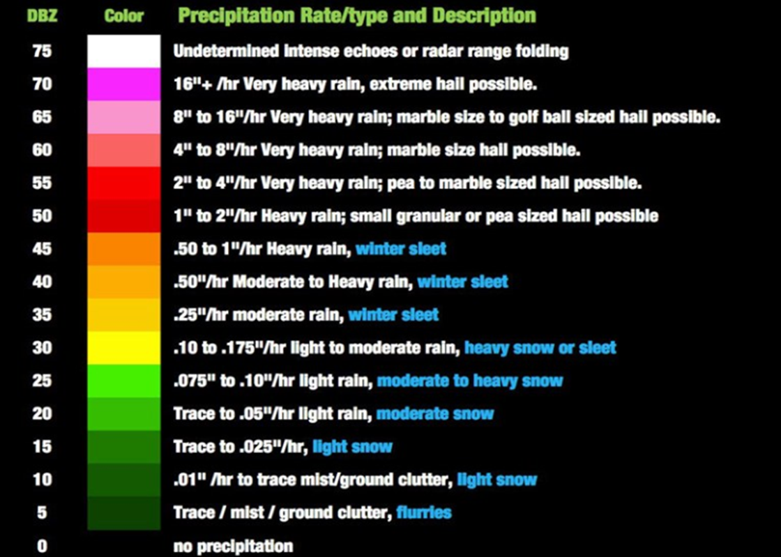
The amount of power received by the radar is usually described by color or level. The colors in a radar image normally range from blue or green for weak turns, to red or magenta for very strong yields. For example, NEXRAD radar sites in the US use the following scale for different levels of reflectivity:
· magenta: 65 dBZ, extremely heavy rainfall;
· Red: 50 dBZ, heavy rainfall;
· yellow: 35 dBZ, moderate precipitation;
· Green: 20 dBZ, light rainfall.
Strong yields (red or magenta) can indicate not only heavy rains, but also thunderstorms, hail, strong winds or tornadoes, but they must be carefully interpreted.
Rain attenuation
The fade of rain primarily refers to the absorption of a microwave radiofrequency (RF) signal by atmospheric rain , snow or ice, and the losses that are especially prevalent at frequencies above 11 GHz . It also refers to the degradation of a signal caused by electromagnetic interference of the front edge of a storm front. Discoloration of rain can be caused by precipitation at the location of the uplink or downlink. It does not have to rain in a location for it to be affected by the blurring of the rain, since the signal can pass through precipitation many kilometers away, especially if the satellite dish has a low viewing angle. From 5% to 20% of rain dimming or attenuation of the satellite signal can also be caused by rain, snow, or ice on the antenna reflector on the ascending or descending link, radom or power horn. Rain Fade is not limited to satellite up or down links, as it can also affect terrestrial microwave point-to-point connections (those on the earth's surface).
Discoloration of rain is usually estimated experimentally and can be calculated theoretically using the theory of scattering of raindrops. The size distribution of raindrops (DSD) is an important consideration for studying the characteristics of rain discoloration. Various mathematical forms, such as the Gamma function, lognormal or exponential forms, are usually used to model DSD. The theory of scattering Mie or Rayleigh with point matching or matrix approach is used to calculate the cross-section of scattering and the specific attenuation of rain. Since rain is an inhomogeneous process in both time and space, the specific attenuation varies depending on the location, time, and type of rain.
The total attenuation of rain also depends on the spatial structure of the rain field. The extent of rain horizontally, as well as vertically, again varies depending on the type and location of rain. It is usually assumed that the boundary of the vertical region of rain coincides with the isothermal 0° and is called the height of the rain. The height of the melting layer is also used as limits of the rain region and can be estimated from the signature of the bright band of the radar reflectivity. [2] It is assumed that the horizontal rain structure has a cell shape, called a rain cell. The sizes of bedbug cells can vary from several hundred meters to several kilometers and depend on the type and location of the rain. The existence of bedbugs of very small size is observed recently in tropical rains. [3]
The possible ways to overcome the effects of rain discoloration are site diversity, power control on the ascending link, variable rate encoding, and reception antennas larger than the size required for normal weather conditions.
The simplest way to compensate for the effect of rain blur in satellite communications is to increase the transmission power: this dynamic blur countermeasure is called uplink power control (UPC). Until recently, power control on the uplink was of limited use because it required more powerful transmitters – those that could normally run at lower levels and be increased to the power level at the command (i.e., automatic). Also, the uplink power control could not provide very high signal margins without compressing the transmission amplifier. Modern amplifiers, coupled with advanced power control systems on the ascending link, which provide automatic controls to prevent transponder saturation, make uplink power control systems an efficient, affordable, and easy solution for rain attenuation in satellite signals.
Meteorological radar equation
To determine the meteorological radar equation, we start from the radiolocation equation, more precisely from a simplified form of the formula for the receiving power:
(1) 
where β – constant dependent on the parameters of the radar system

Pr– the power received
Pe– the power emitted
G – antenna gain
λ – wavelength
r – distance to the target
σ – effective reflecting surface (RCS – Radar Cross-Section)