1. Principle of operation – Continuous emission radars
Continuous Wave (CW) radars emit a very high frequency signal continuously. The echo signal is received and processed, and the receiver (which has its own receiving antenna) is arranged in the same place as the transmitter. Any civil radio transmitter can be used as a radar transmitter if a receiver located at a distance from the transmitter is used, which compares the propagation time of the direct signal with the propagation time of the reflected signal. Tests have shown that the exact position of an airplane can be determined by processing and comparing signals from three television stations.
1.1 Continuous emission radars without modulation
The emission signal of these radars is constant in amplitude and frequency. This type of radars are specialized in determining the speed. Distance cannot be measured. For example, they are used by the police to measure the speed of motor vehicles (radar speedometers). More modern equipment (LIDAR) works in the range of laser frequencies and can do out-of-speed and other measurements.
1.2 Continuous emission radars with modulation
The emission signal is constant in amplitude but modulated in frequency. This modulation again makes possible the principle of measuring the propagation time. Another advantage of these radars is that the reception of signals is done without interruptions and so the measurement results are available continuously. These radars are used to determine not very long distances, when a continuous measurement is required (e.g. when measuring height by planes or for weather radars and for making wind profile).
A similar principle is used by impulse radars whose pulses have long durations, thus affecting the ability to separate in distance. These radars use an internal modulation of the emitted pulses, thus making it possible to improve the distance resolution by the pulse compression method.
1.3 Continuous wave radar – General
Continuous wave radars (CW radars, Continuous Wave radars) emit a continuously transmitted signal. The echo signal is constantly received and processed.
In principle, in a continuous wave radar set, the transmitter works continuously, and an antenna also radiates this continuous signal. There are two basic problems that need to be solved:
· Preventing the direct radiation of the transmitter in the receiver ;
· Assigning the received echoes to a time system in order to be able to perform measurements of the flight time.
Direct irradiation of the transmitter's energy into the receiver can be prevented by:
· spatial separation of the transmitting antenna from the receiving antenna,
for example, the aircraft is illuminated by a powerful transmitter from the ground, and the receiver is located in the rocket that is heading towards the echo to attack the aircraft;
· frequency separation by Doppler frequency for speed measurements.
When receiving an echo signal, it is initially only proof that there is an obstacle in the direction of propagation of electromagnetic waves. From certain properties of the echo signal, the properties of the obstacle can be inferred. For example, the intensity of the echo signal depends on the size of the obstacle. Also, the intensity of the echo signal indicates whether this obstacle
is far or close to the radar. (However, unfortunately, no measurement result can be achieved, since the intensity of the echo signal depends on too many factors). On the other hand, a change in the spectrum is a more reliable indicator of certain properties. For example, reflection from certain materials can also produce harmonics of the transmission frequency. This is specifically exploited in a so-called "harmonic radar" to find people buried under the snow masses in the avalanche areas on the basis of these materials, which are embedded in protective clothing, for example. However, the most commonly used changes in spectrum are caused by the Doppler effect.
Ø As an aside, the Doppler effect is the modification of the frequency of a wave emitted by a source of oscillations in the case of its displacement relative to the receiver. This effect, discovered by the Austrian physicist Christian Doppler (1803-1853), is specific to all types of waves (electromagnetic, sonorous, etc.)
Ø The change in frequency between the source and the receiver is caused by the relative displacement of the source relative to the receiver. If a source of sound waves moves to an observer whose position is fixed, then the observer will receive the sound at a frequency (tonality) greater than the real one. If the source departs from the observer, it will hear the sound at a lower frequency. In both cases, a deviation of the frequency of the waves occurs.
Ø This phenomenon is very easy to see in the case of a car passing by our own right. The frequency of sound waves will change as the car approaches and then moves away from us.
2. Block scheme of a CW radar
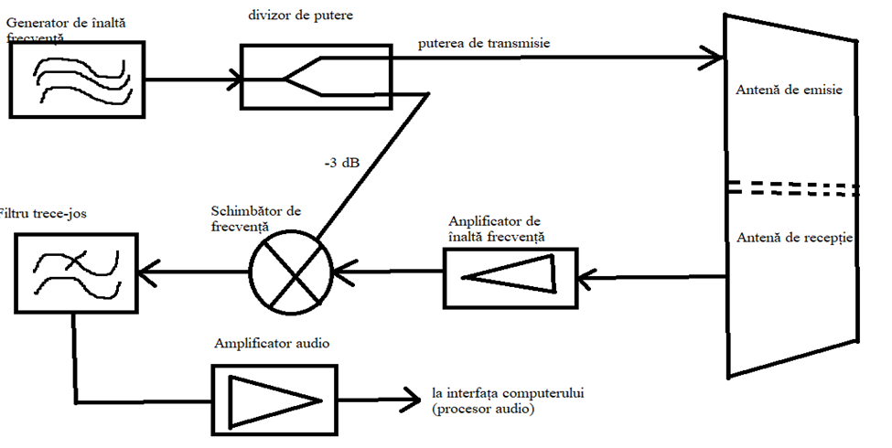
-scall block of a simple radar transmitter-receiver with direct conversion down
3. Advantages (unmodulated Doppler radar applications)
a) Traffic surveillance radar
These continuous wave radars are very specialized. They use the Doppler frequency to measure speed. Since this also depends on the wavelength, these radars operate at very high frequencies in the K-band. For example, the Traffipax Speedophot model, manufactured by ROBOT Visual Systems GmbH, operates on a frequency of 24,125 GHz.
The speed of traffic entering and/or leaving can be measured from the right or left side of the road. The system can be installed in a measuring vehicle or can be operated on a special tripod. Also, the SpeedoPhot system can be used to monitor traffic with the help of photographic documentation of traffic violations.
b) Motion detector
Simple and inexpensive Doppler radar sensors with a circuit like the one shown in Figure 2 can trigger switching functions such as alarms or can simply be used as door openers or switches for lighting.
c) Motion monitoring
The measuring range is not clear: it is not possible to determine how many complete wavelengths are added to the measured fraction. Only a change in a previous value can be monitored.
This method of measurement can be used, for example, for non-contact monitoring of the heart rate and respiratory activity of a patient in intensive care. The radar is directed to the patient's chest and monitors the distance to him with an accuracy of several fractions of a millimeter. Phase changes between the transmitted signal and the received signal are displayed on an oscilloscope as a function of time. A connected computer counts the periodic changes and emits the patient's pulse in numerical form. If no further changes are recorded, an alarm is triggered.
4. LIDAR – radar with continuous emission without modulation
Lidar (sometimes LADAR) is a method for determining ranges (variable distance) by targeting an object or a surface with a laser and measuring the time for the reflected light to return to the receiver. It can also be used to make digital 3-D representations of areas on the Earth's surface and ocean bottom of the intertidal (zona de țărm) and near coastal zone by varying the wavelength (lungime de unda) of light. It has terrestrial, airborne, and mobile applications.
Lidar is an acronym of "light detection and ranging" or "laser imaging, detection, and ranging". It is sometimes called 3-D laser scanning, a special combination of 3-D scanning and laser scanning.
The essential concept of lidar was originated by EH Synge in 1930, who envisaged (avea în vedere) the use of powerful searchlights (reflectoare) to probe the atmosphere. Indeed, lidar has since been used extensively for atmospheric research and meteorology. Lidar instruments fitted to aircraft and satellites carry out (care execută) surveying and mapping – a recent example being the U.S. Geological Survey Experimental Advanced Airborne Research Lidar. NASA has identified lidar as a key technology for enabling autonomous precision safe landing of future robotic and crewed lunar-landing vehicles.
Wavelengths vary to suit the target: from about 10 micrometers (infrared) to approximately 250 nm (UV). Typically, light is reflected via backscattering, as opposed to pure reflection one might find with a mirror. Different types of scattering are used for different lidar applications: most commonly Rayleigh scattering, Mie scattering, Raman scattering, and fluorescence. Suitable combinations of wavelengths can allow for remote mapping of atmospheric contents by identifying wavelength-dependent changes in the intensity of the returned signal. The name "photonic radar" is sometimes used to mean visible-spectrum range finding like lidar, although photonic radar more strictly refers to radio-frequency range finding using photonics components.
· The Mie solution to Maxwell’s equations describes the scattering of an electromagnetic plane wave by a homogeneous sphere.
· Rayleigh scattering named after the 19th-century British physicist Lord Raylegh (John William Strutt), is the predominantly elastic scattering of light or other electromagnetic radiation by particles much smaller than the wavelenght of the radiation.
· Raman scattering or the Raman effect is the inelastic scattering of photons by matter, meaning that there is both an exchange of energy and a change in the light's direction. Typically this effect involves vibrational energy being gained by a molecule as incident photons from a visible laser are shifted to lower energy.
AN/MPQ-64
The AN/MPQ-64 Sentinel is a 3D radar used to alert and cue Short Range Air Defense (SHORAD) weapons to the locations of hostile targets approaching their front line forces. It is an X-band range-gated, pulse-Doppler radar system.
Mounted on a towed platform, it can be positioned remotely from the rest of the unit, operated autonomously and communicate with the Fire Direction Center (FDC) via wideband fiber-optic link. It can also distribute its data over a SINCGARS radio network.
First built in 1997 and currently produced by Raytheon Missiles & Defense, the Sentinel radar is deployed with forward area air defense units of the U.S. Army. It is used as search and track radar in the Norwegian NASAMS air defense system.