1-3. Principle of operation of oscilloscopes. Multichannel, stroboscopic, speed oscilloscopes. Memory oscilloscopes. Oscilloscopes with program control.
1. Purpose, classification and main characteristics.
Two main experimental methods are used in electronic equipment for analysis of electrical signals - time and spectral. The task of time analysis is the qualitative and quantitative study of the dependence of the studied signal on time. The results of this study are usually presented in the form of a graphical dependence of the voltage or current of the signal on time (so-called oscillograph records). The study time can be from fractions of a microsecond to several days. Instruments designed to monitor, measure and record electrical signals are called oscilloscopes.
The electronic oscilloscope is the most widely used device for visual monitoring and recording the shape of time-varying electrical signals and measuring their parameters using a cathode-ray tube (CRT).
There are two main groups of oscilloscopes - electro-mechanical, used to study low-frequency signals (fmax <5-6kHz) and electronic, designed to analyze both low-frequency and high-frequency signals (fmax <10GHz).
The main task of spectral analysis is to determine the spectrum of signals, i.e. in finding the amplitudes and frequencies of the harmonic components of the signal. However, in some cases, for example when measuring nonlinear distortions, it is set as a task determining the amplitude and frequency of the harmonic components of the signal occurring as a result of its passage through the measured system, as well as comparing these components with the components that were in the spectrum of the input signal.
Oscilloscopes are characterized by the following main parameters: screen size, channel sensitivity, maximum voltage of the studied signal, channel bandwidth, input resistance and input capacity, types of time-bases, error in measuring the amplitude and time intervals. Mandatory requirement for oscilloscopes is good brightness and sharpness of the image and high stability of the oscillograph record.
2. General functional diagram.
The main purpose of electronic oscilloscopes is to provide the ability to visually monitor and measure the shape of electrical signals, i.e. the dependence of the studied voltage on time in a wide range of frequencies.
With all the variety of industrial oscilloscopes, their functional schemes are basically the same. The electronic oscilloscope consists of a cathode-ray tube with electrostatic deflection of the beam, two electrical channels through which the voltages for vertical and horizontal deflection of beam, measuring units and power supplies. The channel for vertical deflection and its constituent elements are marked with Y, and the channel for horizontal deflection - with X (For example, "Input Y", "Amplifier X", "Plates Y", etc.). The complete block diagram of a universal oscilloscope is shown in Fig. 3.1.
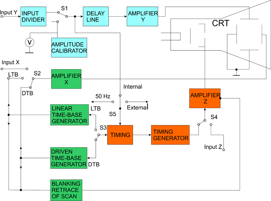
Fig. 3.1
The main blocks are:
Input divider (attenuator) - allows to reduce the value of the tested signal an integer number of times and to match the input resistance of the channel for vertical deflection with the output resistance of the source of the tested signal.
Delay line provides the supply of the examined pulses to the Y - plates of the oscilloscope with a certain delay, in relation to the voltage for deflection of the electron beam, applied to the X - plates.
The vertical deflection amplifier is designed to amplify the tested signal to a level that allows to obtain the required vertical deflection of the electron beam.
The calibrator makes it possible to calibrate the oscilloscope in amplitude and time with the help of fixed pulses.
The horizontal deflection amplifier amplifies the voltages received by the generators for linear and driven time-base. It can also be used as a separate amplifier to amplify a signal applied to input X of the oscilloscope.
The generators for linear and driven time-base produce voltage in the form of a saw. This voltage deflects the electron beam in the horizontal direction.
The blanking retrace scan unit supplies a blanking voltage (rectangular pulse) to the Wehnelt cylinder of the cathode ray tube.
The "Timing" block synchronizes the operating mode of the master generators. In principle, the synchronization can be from the network (50Hz), from the studied signal (internal) or external synchronization.
Z channel - used for special measurements in cases where it is necessary to modulate the electron beam in brightness.
3. Types of time-bases.
Under time-base voltage in the most general case is understood the voltage that determines the trajectory (figure) and the speed of movement of the beam in the absence of the studied signal. The trajectory described by the beam under the action of the time-base voltage is called а time-base.
Oscilloscopes use several types of time-bases that are classified either according to the shape of the time-base voltage or according to the shape of the trajectory obtained under the influence of the time-base voltage. When the time-base voltage is applied to one pair of plates (usually X-plates), the time-base is linear, exponential and sinusoidal (according to the shape of the time-base voltage). If the time-base voltage is applied to the two pairs of deflecting plates (or to the radially deflecting electrodes - in some special CRT), the time-base is circular, elliptical and spiral (according to the shape of the described trajectory). The trajectory described by the beam when applying the time-base voltage to only one pair of deflection plates (regardless of its shape) is always a straight line. In the linear, exponential and sinusoidal development, the investigated voltage is applied to the Y - plates, and in the circular, elliptical and spiral development - to the Wehnelt cylinder or to the second anode.
All these time-bases can be continuous and standby. For the study of continuous periodic processes, it is necessary for the time-base to be continuous, and for the study of non-periodic or periodic pulse processes with a high dilution coefficient a standby time-base is used. It is characterized by the fact that the time-base voltage is applied to the deflection plates only when the input of the pulse from the studied signal. In the absence of such an impulse, the time-base does not work, but "waits" for the next impulse to come.
4. Basic units and elements of oscilloscopes.
With all the variety of industrial oscilloscopes, their functional schemes are basically the same. They include the following main channels and nodes: cathode-ray tube and circuit for its power supply; two electrical channels through which the voltages for vertical and horizontal beam control enter; measuring units and power supplies. Here the composition and the principle of operation of the two channels for beam control in the oscilloscope will be considered.
4.1. Vertical deflection channel.
The vertical deflection channel of the electronic oscilloscope is designed to convert the instantaneous value of the voltage along the Y axis on the CRT screen. It is also possible to hold the signal. It consists of an input device, an amplifier and the vertically deflecting plates of the tube (Fig. 3.1).
A / Input divider.
It provides the set input resistance and expands the dynamic range of the measured voltages. The input resistance of the vertical deflection channel is in the range (0.5-10) MΩ, and the input capacitance is 10-40pF. For some oscilloscopes, a low-resistance input is provided, which is used to study high-frequency or broadband signals. Such signals are transmitted via a coaxial cable connecting the signal source to the oscilloscope. The impedance of such a cable is equal to 50Ω or 75Ω and for its matching at the input of the oscilloscope through the switch S2 the resistor R4 of the resistance is switched on, which is also 50 Ω or 75 Ω.
The circuit and the parameters of the elements of the input divider must ensure the constancy of the division factor in the whole frequency range for which the oscilloscope is intended, the set division factor and the required input resistance. These requirements are met by the compensated divider, the scheme of which is shown in Fig. 3.2.
The error of the division factor must not exceed ± (0,1 - 2) % for the whole operating frequency range. For this purpose, it is necessary to have equality of the input time constants at each position of the switch S1. The criterion for the accuracy of compensation is the absence of a distorted shape of the test rectangular pulse passed through the divider. If the capacitance of capacitor C is less than necessary, then the duration of the pulse front increases, if it is larger - rebounds occur.
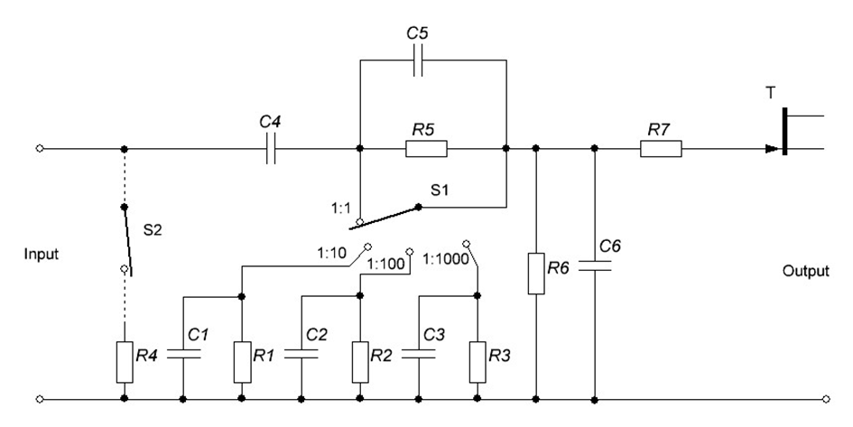
Fig. 3.2
The voltage dividers are graduated in the values of the division coefficients n (n = 1; 10; 100) or in the values of the units of the scale of the CRT screen along the Y axis in [V / cm], [mV / cm] or [ V / div], [mV / div], where "div" - division of the scale network. This makes it possible to perform direct digital reading of the voltage of the measured signal by multiplying the ordinate of the oscillography record by the value of the scale.
B/ Vertical deflection channel amplifier.
It is designed to expand the dynamic range of the studied voltages in the region of their small values. The amplifier must provide the set gain at the required frequency band, minimum amplitude and phase distortions and symmetrical output voltage. The gain is determined by the required sensitivity of the oscilloscope and is achieved by the appropriate choice of the number of gain stages and their circuit solution. The sensitivity of the oscilloscope S0 is determined by the product of the sensitivity of the tube ST and the gain k, i.e. S0=k.ST
The sensitivity ranges from 10-25mm / V for low sensitivity oscilloscopes and up to 1 mm / μV for high sensitivity oscilloscopes. In the first case, one or two-stage amplifiers with a gain of 25-50 are used, and in the second - multi-stage amplifiers with a gain of several thousand.
Resistive amplifiers with low and high frequency correction are the most common. Such amplifiers usually consist of several stages (Fig. 3.3) for pre-amplification, phase inverse and final stage. The first stage is performed according to the emitter-follower amplifier, which provides a large input resistance and a small input capacity of the amplifier. The phase-inverse stage is often performed in a simple split-load scheme. The final stage must create two symmetrical anti-phase voltages at its output and have a small output resistance. Such stages are called paraphase.

Fig. 3.3
As noted, vertical deflection amplifiers are subject to strict requirements regarding the constancy of the frequency response, the gain, the absence of phase and nonlinear distortions. In an amplifier, as a rule, both a large gain and a wide bandwidth cannot be achieved at the same time. At the same time, in practice, problems often arise related to the need to study relatively narrowband signals with small amplitude. To expand the operational capabilities of electronic oscilloscopes, some of them are produced with replaceable blocks of the vertical deflection channel.
A special device - a delay line - is introduced in channel Y of the oscilloscope. This line, when the input signal and the time-base generator are applied simultaneously, delays the signal input to the plates Y until the time-base voltage appears on the plates X.
In order to expand the operational capabilities of oscilloscopes, special measuring transducers are added to them, with the help of which can be performed current oscillography, selection of random processes, study of the frequency characteristics of the resistors, switching of the studied voltages.
4.2. Horizontal beam deflection channel.
This channel serves to create time-base voltage. It consists of an input device, a horizontal deflection channel amplifier, a time-base generator and horizontally deflecting CRT plates. The time-base voltage, as seen in Fig. 3.1, can come from an external source and from the time-base generator. In the mode of studying the shape of the signals, the internal time-base voltage is mainly used, for which it is generated by a generator for linear time-base of the oscilloscope.
A/ Input device.
It provides the set input resistance and attenuation (if necessary) of the voltage from the external source connected to input X of the electronic oscilloscope. Thus, the functions of this device are analogous to the functions of the input device of the vertical channel deflection, as its parameters are much lower. For example, the input resistance does not exceed (0.05 - 0.5) MΩ, the divider has two or three degrees of division, the error of the division coefficient is not normalized.
B/ Horizontal deflection channel amplifier.
This amplifier generally has the same block diagram as the vertical deflection channel amplifier. It amplifies the voltage drawn by the external time-base generators connected to input X of the electronic oscilloscope. In the mode of operation of an internal time-base generator, the amplifier is used to increase the synchronizing voltage or trigger pulses required to control the operation of the time-base generator.
The parameters of the amplifier of the channel for horizontal deflection differ significantly from those of the amplifier for vertical deflection, it has a lower gain and a narrower range of operating frequencies. This must be taken into account when operating the oscilloscope in external development mode.
C/ Generator for linear base-time.
Serves to generate linearly changing over time (saw-shaped) voltages for time-base. The functional diagram of such a generator is shown in Fig. 3.4. It consists of a timing unit, a time-base generator and an amplifier, which amplifies the voltage of the time-base generator and ensures symmetry of the output voltage. In some cases, the sync unit and the amplifier may be missing. Time-base generators operate in two main modes - continuous and standby. According to the principle of reliability, there are two types of generators for time-base of relaxation type and integrating. They are performed on ion devices, electronic lamps, transistors and integrated circuits.
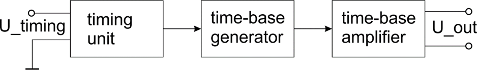
Fig. 3.4
Time-base generators produce linearly increasing or linearly decreasing voltage, which is characterized by the following main parameters: maximum value Umax; time of retrace of scan τ; minimum value Umin and coefficient of nonlinearity δ. The time of the time-base of modern oscilloscopes is within limits from parts of ns / cm (ns / div) to tens of s / cm (s / div).
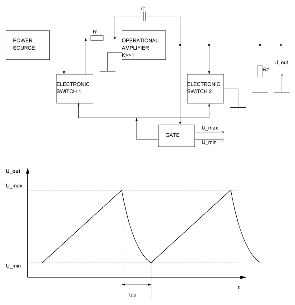
Fig. 3.5
Integrative type time-base generators allow to obtain a small coefficient of nonlinearity (up to 0.1%). The change of the frequency of the generator is usually carried out only discretely by the switching path, the capacitances of the C and the resistances of the R. The graduation of the generator is usually done in values of the time-base q.
In driven time-base mode, the time-base generators produce a linearly varying voltage only when the input of a trigger pulse from an external source. This voltage is applied to the input of the timing unit and after gain a steep front is obtained to ensure high start speed. If necessary, the timing unit not only amplifies the external voltage, but also its differentiation, which allows to further shorten the start time of the time-base generator. Each trigger pulse will cause a cycle of oscillations of the time-base generator.
To switch the time-base generator to driven time-base mode, it is necessary to break the positive feedback circuit, which provides the self-oscillating mode of operation. To switch to driven time-base mode of the integrating time-base generator (fig. 3.5) it is necessary in the gate device to exclude the lower trigger threshold. The activation of Electronic Switch 2 is carried out by the trigger pulse.
A peculiarity of the operation of the cathode ray tube and in the driven time-base mode of the time-base generator is the blanking of the electron beam during the "waiting" and the sharp increase of its intensity during the straight course of the time-base. Blanking the beam in driven time-base mode prevents the CRT screen from burning out in the event of a long pause. The illumination of the beam is provided by applying a positive pulse to the modulator during the straight course of the development.
D/ Amplitude calibrator.
Represents a generator of a sample value variable voltage intended to check (and if necessary to establish) the correctness of the scale on the Y axis, the scale of the tube screen or to measure the signal voltage.
In accordance with these functions, we distinguish two main groups
calibrators: with a constant calibrated voltage amplitude and with a smoothly varying output voltage amplitude. Calibrators from the first group have found wide application in modern oscilloscopes. They are rectangular pulse generators with a frequency of 1-5kHz. The amplitude of the pulses is stabilized by stabilitrons (Fig. 3.6) with an error not greater than ± (0.5 - 1) %.
In calibration mode, voltage is applied to the input of the channel from the calibrator and with the help of the input voltage divider the set scale of the vertical deflection channel is established, at which the oscillograph record sweep along the Y axis must be equal, and a certain value, usually marked of the large-scale network on the screen.
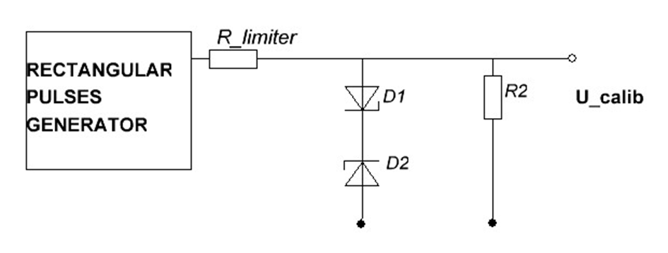
Fig. 3.6
Calibrators of the second group are usually built according to the scheme of the unbalanced bridge, which allows to obtain a smoothly adjustable voltage from the network. This voltage is determined on a graduated scale of the potentiometer or measured with a voltmeter. The measurement is made by the method of comparison.
E/ Calibrator by duration.
It is designed to check (and if necessary to establish) the duration of the time-base of the electronic oscilloscope. It is a source of sinusoidal signals with a sample (reference) frequency, the period of which is a working measure of time.
Two types of calibrators are used in electronic oscilloscopes: constant sample frequency calibrators to check and scale the duration of the time-base, and calibrators with several fixed frequencies, designed for direct measurement of the duration of the oscillograph record.
The calibrator of the first type is a generator, the frequency of which is usually equal to 105 or 106 Hz. Quartz frequency stabilization is often used to increase accuracy. The calibrator voltage is applied to the input of the vertical deflection channel. The duration switch is set in such a position that a set number of periods is set on the set section of the large-scale network (Fig. 3.7) to correspond to the nominal length of the time-base.
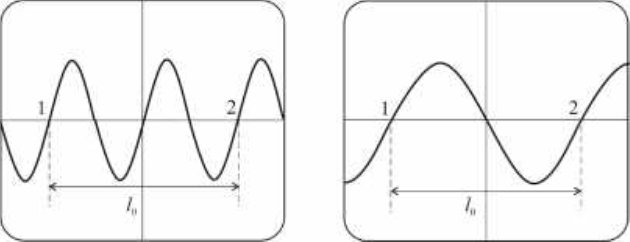
Fig. 3.7.
If the duration of the time-base turns out to be longer than nominal, then more than two periods of the oscillograph record will be located on the segment. The error is conveniently corrected by smoothly adjusting the voltage Um of the time-base generator.
Because the error in the calibration of the duration of oscilloscope is small, then the required voltage change limits do not exceed ± (5-10) %. The error of calibrators of this type is ± (1-2) %.
Duration calibrators with several fixed frequencies are used to measure the duration by modulating the brightness of the oscillograph record. The output voltage of the calibrator is applied to the modulator of the tube (channel) and causes an increase or decrease in the brightness of the oscillograph record in the positive and negative halves, respectively. As a result, the oscillograph record takes the form of a broken line. Dark and light sections of the line are called bookmarks. The duration of the mark corresponds to one period of the calibrator voltage and is indicated on the calibrator sub-switch in [ms] or [μs]. The duration of the marks is established so that their number on the oscillograph record of the tested voltage is as large as possible to increase the accuracy of the measurement. To obtain the CRT screen of fixed marks, it is necessary to accurately synchronize the voltage frequency of the time-base generator with the voltage frequency of the calibrator by duration.
The main error in measuring the signal duration with such calibrators is usually ± (5-10) %.
5. Special types of oscilloscopes.
5.1. Multichannel oscilloscopes and electronic switches.
Very often there is a need to observe two or more electrical processes simultaneously. This problem can be solved in two ways:
- When a separate electron beam is used for each process - multichannel oscilloscopes.
- When the same beam is periodically switched to each process.
A/ Multichannel oscilloscopes.
The main point by which multichannel oscilloscopes differ from ordinary ones is the specificity of the cathode ray tubes. The two-beam tubes (fig.3.7) consist of a glass flask in which two separate electron beam systems and respectively two deflection plate systems (ХА-ХА; YA-YA; ХB-ХB; YB-YB). These systems form two electron beams that act on a common screen E.
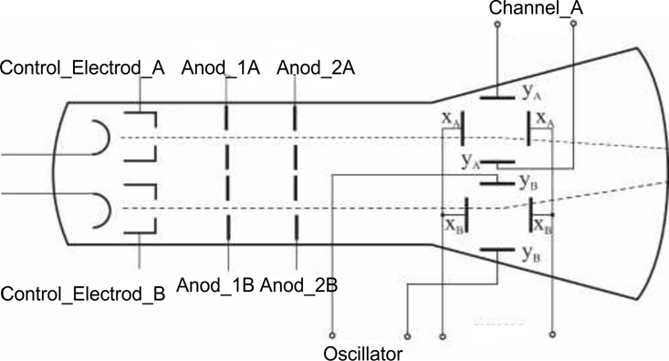
Fig. 3.7.
The individual signal amplification channels are usually implemented with differential amplifiers. This allows the use of two-beam oscilloscopes for a number of complex measurements.
The two-beam oscilloscope has a common time-base generator, the voltage at which it is applied to the two pairs of X-plates by a common horizontal deflection amplifier. It has two vertical deflection channels, each of which contains all the units of the vertical deflection channel of the single-beam oscilloscope.
In principle, the operation of a two-beam oscilloscope does not differ from the operation of an ordinary oscilloscope. The two-beam oscilloscope is convenient for studying non-stationary processes.
B/ Electronic switch (ES).
Two (or more) processes with the same or different frequencies can also be observed on the screen of a simple electronic oscilloscope if a special electronic switch is used. Through it, the examined signals are sequentially switched to the Y-plates of the oscilloscope. The switching frequency must be such that the eye is unable to notice the change in the oscillograph records. The block diagram of an electronic switch, as well as the principles of switching are shown in Fig.3.8. The voltages of the two signals U1 and U2, which will be monitored, are applied to two independent amplifiers (Y1 and Y2 which work with a common load.
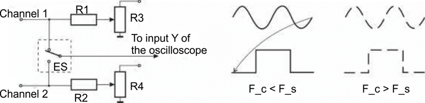
Fig. 3.8.
During operation of the electronic switch, the curves of the tested voltages can be observed on the oscilloscope simultaneously, without sudden shifts, only provided that their frequencies are different or multiples of Fs1, = nFs2 (multiplier n = 1,2,3,4…). In these cases, the oscilloscope time-base generator is synchronized with the lower frequency.
When the switching frequency is equal to or lower than the studied signals Fc < Fs, (for simplicity of consideration is accepted, their oscillograph records are obtained continuous, and when it is higher than this frequency (Fc > Fs) - broken lines.
With the described electronic switch, two processes can be observed simultaneously. It is possible to design an electronic switch to monitor three or more processes. In this case, more complex EC schemes are used, which allow them to be blocked one after the other several amplifier stages.
6. Stroboscopic and speed oscilloscopes.
6.1. Stroboscopic oscilloscopes.
It is not possible to use ordinary oscilloscopes to observe very high frequency processes or pulses with a very short duration and a high repetition rate due to difficulties of the properties of CRTs, amplifiers and time-base generators. Therefore, special micro oscilloscopes, speed oscilloscopes, stroboscopic oscilloscopes are used to study such signals. In high-speed and micro oscilloscopes, the CRT has a special design in order to avoid parasitic capacities, to reduce the influence of the time for the electrons to fly over, etc. They use distributed amplifiers (with traveling wave) and high-speed time-base generators. Due to the reduced size of the oscillograph records, they are monitored with the help of optical instruments. In general, these oscilloscopes are complex, expensive and inconvenient to operate.
Recently, stroboscopic oscilloscopes have been widely used in the study of periodic signals and nanosecond pulses. They are built on a completely different principle, which makes it possible to study high-frequency processes with a simple oscilloscope.
The stroboscopic principle of oscillography is reduced to transforming the time scale of the studied signal (pulse), i.e. to artificially stretch the signal over time without changing its shape. Moreover, as is known from the theory, the more times the signal expands, the more times its spectrum narrows. This circumstance allows the use of an ordinary oscilloscope. In practice, the signal can be stretched tens of thousands of times.
The stroboscopic principle of oscilloscope is similar to the principle of stroboscopic observation of a uniformly rotating disk when illuminated by short light gating pulses, repeated periodically at a frequency close to the rotational frequency or close to the reduced number of times the rotational speed of the disk. In this position, the rapidly rotating disk will appear to be slowly rotating, so it can be studied in detail (Fig. 3.9).
In stroboscopic oscillography, the fast-moving periodic process seems to be illuminated like a disk, with the help of extremely short gating (probing, selective) pulses with a repetition rate close to the frequency of the studied process or close to the reduced integer frequency. In Fig. 3.9 it can be seen that during the stroboscopic oscillography of the screen not all moment values are fixed, but only a certain number of discrete values, spaced apart from each other on the interval Δt (sampling interval). The smaller this interval, the more accurate the reproduction of the studied signal.
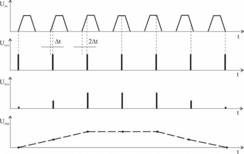
Fig. 3.9.
It can also be seen from the figure that in order to obtain a fixed oscillograph record, it is necessary for the period of the studied signal to be a multiple of the sampling interval (Τ = nΔt). The same does not apply to the duration of the pulses, although in the figure a case is chosen in which t_pulse = n.Δt.
6.2. Speed oscilloscopes.
The expression for the static sensitivity of the cathode ray tube is valid at low frequencies, when the phase of the applied voltage does not change during the time of flight of electrons between the deflection plates. At ultra-high frequencies, the effect of this time must be taken into account. In such cases, the sensitivity is defined by the expression:
where - dynamic sensitivity;
- static sensitivity;
- frequency of the studied oscillation;
- time of flight of electrons.
It is obvious that if the time equals the period T = = 1 / f of the studied signal, the dynamic sensitivity will almost be canceled. This means that there will be no beam deflection.
There are two ways to overcome the negative effect of the final electron flyover time.
The first of them uses reduced geometric dimensions of the deflection plates. With the help of special electronic optics and high acceleration, a quality image is achieved. On this basis, unique micro oscilloscopes have been developed, which have limited application in physics.
The second method is based on the use of a special cathode ray tube. These are traveling wave tubes. These tubes make it possible to achieve an equality between the speed of propagation of the electromagnetic wave along the Y deflection system and the speed of the beam. In this way, not only the harmful effects of the time of electron flight are neutralized, but also the studied signal is amplified.
Fig. 3.9 shows the supply of such a tube. The defection system is implemented in the form of a delay line. It is coordinated at the input and output according to the impedance Zc.
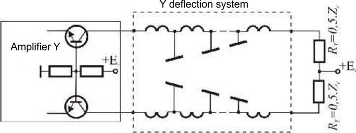
Fig. 3.9.
6.3. Memory oscilloscopes.
The use of memory oscilloscopes significantly increases the efficiency in the experimental study of many processes. These oscilloscopes allow electrical signals to be stored and subsequently reproduced, analyzed or stored repeatedly for transmission to another medium. By their principle of operation, these devices can be analog or digital.
6.3.1. Analog memory oscilloscopes.
This type of oscilloscope stores the studied signal in analog form. In terms of design, this type of oscilloscope differs from the universal only in the device and operation of the cathode ray tube. In this type of tube, in addition to the classic electronic gun, one or two guns are placed for reproduction.
Fig. 3.10 shows such a tube. The gun for recording is marked with G, and the guns for playback are marked with G_p. They are usually mounted at the level of the last pair of deflection plates. They are attached to the final guiding electrode (collimator). Playback guns emit divergent electron beams with relatively low kinetic energy. Their supply voltages are selected in such a way that the extension of the electronic flow covers the entire screen. The system of collimators with consistently increasing potentials plays an essential role in the channeling of the rays.
Memorization is carried out with the help of a special target Т. It is a dense metal grid, covered on the side of the guns with a thin layer of dielectric. When bombarded with fast electrons, this dielectric releases a large amount of secondary electrons, which are collected from the collector array. A positive voltage of the order of + (100-150) V is applied to this grid. The potential of the target is close to zero. The screen is covered with a thin layer of aluminum and is connected to a high voltage rectifier (up to +5 kV).
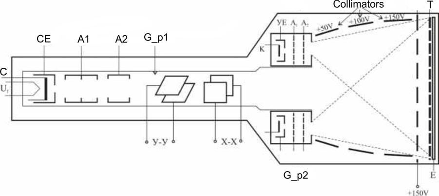
Fig. 3.10.
In the initial state, the surface of the dielectric in the target is negatively charged by the slow electrons falling on it, coming from the rays of reproduction. Their speed is low and cannot cause secondary emissions. When an electron beam is applied to the target, describing the shape of the process under study, it causes a secondary electron emission at the bombed sites. They are positively electrified and create conditions for easy passage of slow electrons from the reproducing guns through the space immediately around them. It is as if the main beam "appears" on the target a hole in the form of the studied signal, which "illuminates" and projects on the screen of the tube from the two searchlights for reproduction. The penetrated slow electrons are accelerated by the high voltage applied to the aluminum plate on the screen. Hitting the phosphor, they cause a glowing image that corresponds to the image drawn by the main beam. In this case, it is not the writing beam but the playback beams that project the oscillograph record onto the screen. Therefore, it can be observed even after the removal of the studied signal. Moreover, since the localized positive charges on the dielectric surface are preserved for a long time, the oscilloscope can be switched off and after a new switch-on the studied process can be observed again.
6.3.2. Digital memory oscilloscopes.
Digital memory oscilloscopes undoubtedly have advantages over analog ones - practically unlimited duration of the stored information and possibility for delayed reproduction of separate sections of the oscillograph record. In addition, these oscilloscopes have the simplicity of managing and extracting information in digital form with the possibility of processing by processor. The block diagram of a digital memory oscilloscope is shown in Fig. 3.11. A feature of this type of oscilloscope is that it can operate in two modes. When the switch is in position 1 like a normal oscilloscope, in position 2 of the switch the device operates as a digital storage oscilloscope. In this case, the signal from the input via the ADC enters the storage device. When the conversion is complete. the controller receives a control signal from the ADC, which controls the time-base generator.
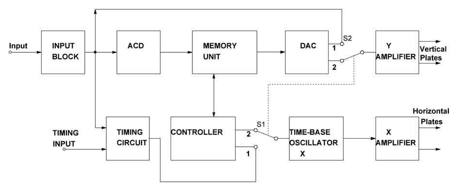
Fig. 3.11.
The signal is fed to the DAC from the memory unit. In position 2 of the switch, the signal received from the DAC output is fed through the Y amplifier to the vertical deflection plates. This type of oscilloscope allows the recorded digital image of the electrical signal to be transferred to a suitable medium and then entered into a graphics program with which to process or analyze.
In addition to the above scheme, other structural schemes are used in practice. The main thing with them is that the time-base generator has been replaced with a DAC, which produces step-varying voltage. This voltage, after amplification by the X amplifier, is applied to the plates for horizontal deflection.
6.4. Oscilloscopes with program control.
One of the first "intellectual", i.e. programmable oscilloscopes are a combination of an ordinary oscilloscope and a digital processing and control system - a microprocessor system.
Figure 3.12 shows a simplified block diagram of an oscilloscope of this type. The figure clearly shows the two main blocks of classical oscilloscopes: a channel for vertical and a channel for horizontal deflection.
The main connecting links between the analog part of the oscilloscope and the microprocessor system are ADC and DAC. The need to remember the signal while maintaining a high resolution also determines the specifics of analog-to-digital conversion. These are sampling of the analog signal with small intervals (high frequency) and quantization with a larger number of levels.
If a 10-digit ADC is used, the highest resolution on the horizontal and vertical axis of the screen is 1/1024 (0.1%). To achieve such high characteristics for oscillography of signals with a frequency band up to 400MHz requires 10-bit ADC and sampling with a frequency not lower than 1GHz. Modern ADCs do not have such speed and in most cases uneven sampling is used. In most cases, ADCs with bit balancing are used, which have a conversion time.
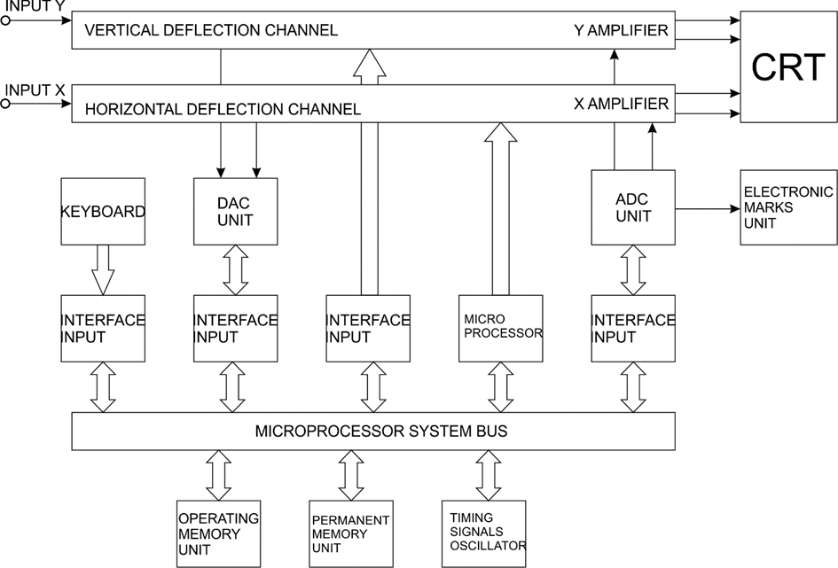
Fig. 3.12.
The great capabilities of computer technology allow to perform various operations on the recorded image such as: zooming; text input; marking certain areas of the image; cropping a certain part of the image, etc.