Measurement in telecommunications
Content
Voltage measurement at medium and high frequencies. General information, requirements and characteristics. Functional diagrams and principle of operation of analog electronic voltmeters.
1 Voltage measurement at medium and high frequencies.
1.1 General information and requirements.
The measurement of voltage in electronic circuits in telecommunications differs from similar measurements in electrical (power) inspections. This is due to the specific features of the electrical signals used in telecommunications as:
a) Extremely wide frequency range - from constant voltage and infrared frequency (parts of hertz) to high frequencies (1GHz and more);
b) Wide range of voltage measurements by value (from parts of a microvolt to tens, even hundreds of kilovolts);
c) Measures voltage in communications is difficult because uses a lot of voltages of different shapes. This requires the use of different methods. In most cases of voltage measurement, the shape of the voltage must also be observed.
The measurement is complicated by the fact that voltage amplitude, as a rule is small. This does not allow power to be provided by the meter. Otherwise, the device will affect the operation of the circuit - will change the configuration of the circuit.
There are two main types of DC and AC voltmeters. The first group of devices uses a scale (dial) for indication. The second type is automatic digital voltmeters. They evaluate the results of the measured quantity in the form of discrete figures.
In the process of measuring high and high frequency AC voltages, it is maintained with maximum (amplitude), root mean square (effective), mean and average value.
a) Maximum value ( ) or amplitude (for harmonic signals) is the largest instantaneous value of the voltage for the observation time (or for one period). For bipolar curves, two maximum values ( are distinguished: positive - and negative -.
b) Root mean square (RMS, also called effective). To be determined as the root mean square value of the amplitude values of the voltage for the time of measurement (or for one period) and is defined by the expression:
.
The RMS value of the voltage measurement is of interest in the process of measuring the sinusoidal AC voltage. This value is equivalent to such a constant voltage applied to the load, due to which the amount of heat is released on the resistive load, as well as the application of the alternating voltage.
The effective value of periodic voltage with non-sinusoidal shape is equal to:
where are the effective voltages of all acting harmonic oscillations.
c) Mean value (constant component). To determine as the arithmetic mean of the instantaneous value of the voltage for the time of measurement (or for one period):
d) Average value. To determine from the absolute value (modulus) of the instantaneous values of the alternating voltage by the expression:
If , the mean value (constant component) is equal to the area bounded by the voltage curve. At unipolar voltages, the mean value (constant component) is equal to Average value. At bipolar voltages, these two quantities are different. For example, for a harmonic sinusoidal voltage , .
The relationship between the maximum (amplitude) and the RMS (effective) value of the voltage is determined by the amplitude coefficient:
The ratio between the effective and the average DC voltage determines the form ratio:
.
For periodic signals, depending on the signal form, these coefficients are different values, for example:
- At sinusoidal voltage - ; .
- At voltage with saw shape - ; .
- With a rectangular shape with symmetrical half-periods - ; . This means that .
1.2 Functional diagrams of electronic analog voltmeters.
The electronic voltmeters, in principle of operation in basic lines, are performed according to two block diagrams: detector-amplifier of direct current - indicator (fig.1, a) and amplifier of alternating current - detector - indicator (fig. 1, b).
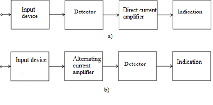
Figure 1
Voltmeters of the first type are designed to measure constant and alternating voltage from tens of parts of volts to several hundred volts in a wide frequency range. Typically, these voltmeters measure voltages with a frequency range from a few hertz to a few hundred megahertz - (700 - 800 MHz).
Voltmeters of the second type are used to measure AC voltage. They usually have a higher sensitivity of up to a few microvolts, the upper limit is up to a few tens of volts. The frequency range of these voltmeters is significantly narrower - the upper limit does not exceed a few hundred kilohertz. In rare cases, voltmeters up to several megahertz are produced.
The main advantages of electronic voltmeters are:
1. Insignificant power consumption of the measured object - more precisely, they are characterized by high input resistance and small input capacity.
2. Low dependence of the frequency in the operating frequency range.
3. High sensitivity with a significant range of measurements.
4. Ability to withstand overload (voltage at the input of the device may exceed the allowable).
Schematic and design features of analog electronic voltmeters.
As noted, electronic voltmeters for alternating voltage are realized in two main structural schemes:
- with preliminary detection;
- with alternating current amplification.
In pre-detection voltmeters, which are used to measure high-frequency voltages, the AC voltage is pre-converted to DC, and then measured with an electronic DC voltmeter. This is due to the fact that for frequencies above 1MHz it is not possible to create sufficiently accurate measuring amplifiers.
The converter of these voltmeters is an amplitude diode detector with a closed input, which can be made with high input impedance. To avoid the capacity of the connecting cable, the detector is placed in a metal box (probe, probe at the beginning of the cable). Input capacity of the detector, ie. per voltmeter, can be reduced to a few picofarads.
Due to the presence of an amplitude converter these voltmeters will always be proportional to the amplitude of the measured voltage, regardless of its shape. For convenience they are graduated to an effective value.
For this reason, when measuring a sinusoidal voltage with a high coefficient of nonlinear distortion, large errors will occur. Pre-detection voltmeters have the best frequency properties and are used for measurements in the range from 10Hz to 2000MHz with an accuracy of 2-3%. However they do not have high sensitivity because they do not amplify the AC voltage. Their smallest nominal range is about 1V, for the range up to 10V they have nonlinear (individually graduated) scales, which is due to the nonlinear volt-ampere characteristic of the diode in the forward bias and can measure voltage up to 1000 - 1500V. Their input impedance consists of a resistance connected in parallel to a capacitance
AC voltmeters consist of an attenuator, an AC amplifier and an average, maximum or effective value detector with a pointer voltage meter. These voltmeters are characterized by high sensitivity and high input impedance.
The range of electronic voltmeters for alternating voltage is realized with frequency compensated dividers. Figure 2 shows a divider for expanding the frequency range of an electronic voltmeter, consisting of the reference resistors and . Parallel to is the input impedance ( , ) of the measuring amplifier. The variable capacitor is switched on to avoid the frequency error of transmitting the to the attenuator.
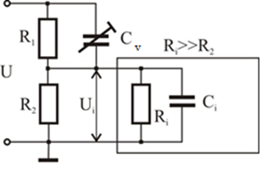
Figure 2
Electronic gain voltmeter detectors are usually average. They are included in the negative feedback circuit, along with indication system. This is done in order to obtain greater linearity on the scale of the electronic voltmeter. On the other hand, such switching allows a significant overload of the voltmeter.
One such scheme is shown in Fig. 3 voltages and currents are denoted by their instantaneous values. It is assumed that the amplifier operates in the frequency range for which the gain is a real number. It is also assumed that the amplifier has an infinitely large input resistance ( ).
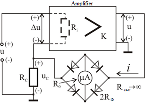
Figure 3
The feedback voltage is proportional to the current through the magnetoelectric microammeter with resistance . The current can be expressed:
usually
It follows from this condition that:
The last expression shows that the scale of the voltmeter will be linear and does not require individual calibration. This independence of indication system from the resistance of the diodes is a great advantage of these electronic voltmeters.
In cases when operational amplifiers are used in electronic voltmeters, it is necessary to take into account some peculiarities when switching on the detecting element (converter). The most common scheme of such a transducer, when the measuring element is a switching device, is shown in Fig.4.
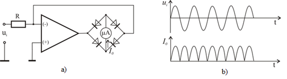
Figure 4
It can be seen from the diagram that the negative feedback to the inverting input of the amplifier is realized by means of a bridge measuring circuit in the diagonal, on which a switch is connected.
This circuit is characterized in that the additional processing of the output voltage of the converter is associated with significant difficulties due to the indeterminate potential of the two output terminals of the converter. Fig. 5a shows a diagram of a one- cycle converter of absolute value, at which the output voltage is fixed relative to the zero potential.
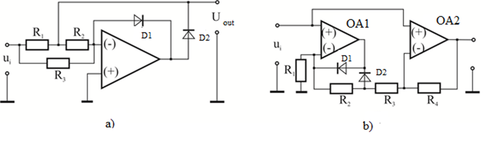
Figure 5
For the positive half-cycles of the input voltage the feedback is carried out through and for the negative ones - through .
The following circuit diagram of an absolute value converter with an operational amplifier is shown in Fig.5, b. The scheme is also functionally different for the two halves. This feature introduces asymmetry at high frequencies. That is why this circuit is mainly used for relatively low frequencies.
The circuit of the converter shown in Fig. 6, a is relatively simpler. A significant disadvantage of the shown scheme is the large difference in the output resistance for the two periods. In some cases, a two cycle converter uses two operational amplifiers for absolute value. Such a scheme is shown in Fig 6, b.
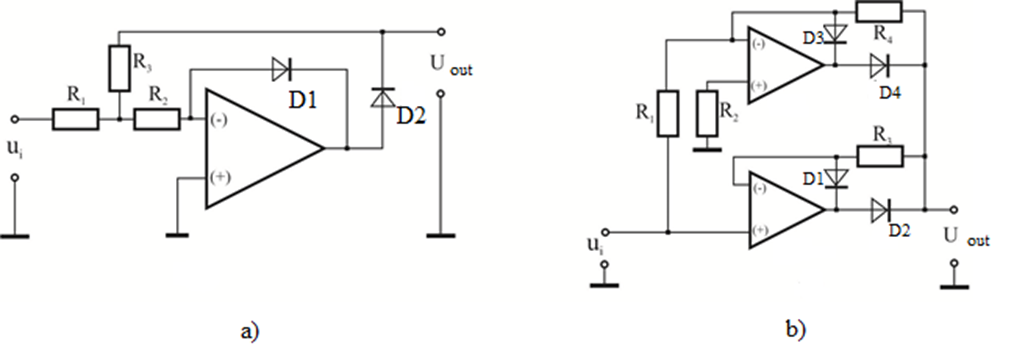
Figure 6
Analog voltmeters in which the amplifier element has selective properties and can be tuned to a certain frequency are called selective voltmeters. Selective voltmeters are extremely widely used in the tuning of telephone channels, radio relay lines, transmitters and more. in which the signal is mixed with interference. These interferences are suppressed by the selection of the input signal by frequency. It is not the total input voltage that is measured, but only the value of the input voltage with a certain frequency (or more precisely for a certain narrow frequency band). There are a variety of schemes for such selective voltmeters. Depending on the technical conditions and operating conditions, a single, double and sometimes triple frequency conversion is used. Figure 7 shows the block diagram of a selective voltmeter.
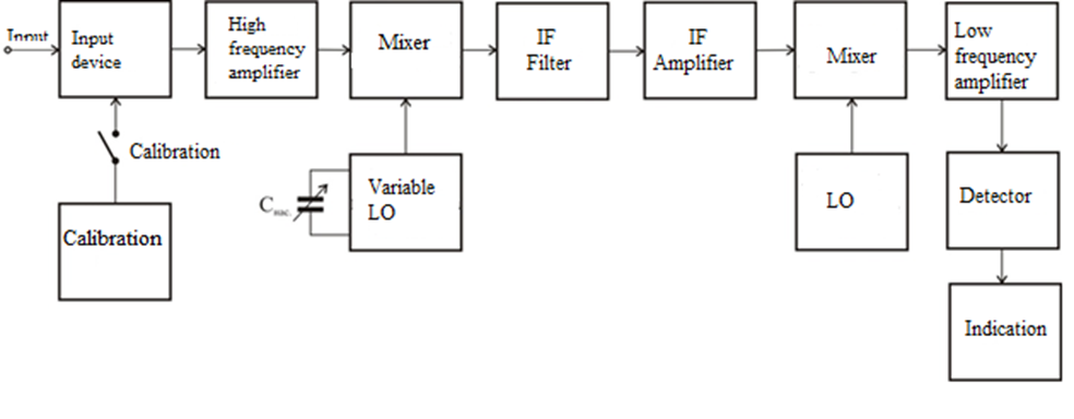
Figure 7
The circuit has a double frequency conversion and is designed to measure voltage with a certain frequency. The input device provides the required input resistance and input signal voltage. The secondary frequency conversion stage consists of a constant frequency local oscillator, a frequency converter and a quartz filter, which determine the bandwidth and selective properties of the voltmeter. The level calibrator is used to exclude the systematic error caused by the instability of local oscilator voltages, the change of the gain of the amplifiers, the temperature fluctuations of the circuit parameters and the calibration is performed after preheating instrument immediately before the measurement.
1.3 Digital electronic voltmeters.
In the case of digital electronic voltmeters (DEV), the measurement result is given in discrete form (digital form).
The main advantage of digital measuring instruments over analog ones is the high accuracy of measurement. In ordinary DEVs it is about 0.1% accuracy, having only the most precise analog devices, and there are DEVs with an accuracy of 0.001% and even higher.
While analog instruments perform one measurement in a few seconds, DEVs can perform up to several hundred thousand measurements per second, and there are special high-speed DEVs that perform millions of measurements per second.
DEVs allow the introduction of automation of the measurement process. In order to perform the measurement with digital electronic voltmeters, it is only necessary to supply the measured voltage. The range selection and polarity indication can be done automatically. The calibration process is also automated - there are DEVs with automatic calibration of the zero and full range.
Automatic switching of polarity and voltmeter ranges also reduces operator error. Many of these voltmeters have outputs for continuous recording of measured quantities by means of typewriters and tape perforators, as well as by magnetic recording equipment. Data in digital form can be processed computer without compromising the accuracy of the measurement.
In addition to DC voltage, digital voltmeters can also measure AC voltage, DC current and resistance. These functions require additional signal processing, after which they can be measured by a digital voltmeter for constant voltage.
The main unit of digital electronic voltmeters is the analog-to-digital converter (ADC). It converts the voltage into a digital code. According to the type of converted voltage, ADCs can be divided into ADCs for DC voltage, AC voltage and pulse voltages.
Typically, digital electronic voltmeters practice first converting AC voltage to DC voltage and then using ADC for DC voltage. For this reason electronic voltmeters will be considered for DC voltage only.
Analog-to-digital converter converters for DC voltage can be grouped into two main groups - with indirect voltage conversion and with direct conversion. In the first group, the converters convert the voltage into frequency, time interval and phase. In the second group, the voltage conversion is done directly in code, as the conversion is done with sequential balancing, with parallel conversion and conversion with a counter and digital-to-analog conversion (DAC).
Digital electronic voltmeters usually have a name that is determined by the type of conversion. The most common types of electronic voltmeters are: digital voltmeter with time-pulse conversion; digital voltmeter with code-pulse conversion; digital voltmeter with bit coding (balancing); continuous balance digital voltmeters and integrating digital voltmeters.
1.3.1 Functional diagrams and principle of operation of digital electronic voltmeters.
1. Digital voltmeter with time-pulse conversion.
The principle of operation of the digital voltmeter with time-pulse conversion consists in measuring the time for which a linear sawtooth voltage changes from the level of the input signal to zero. This time interval is proportional to the measured input voltage.
The timing diagram in Fig. 8 illustrates the method of conversion. The sawtooth voltage is continuously compared to the unknown voltage being measured.
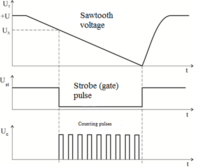
Figure 8
At the moment when the sawtooth voltage and the unknown voltage equalize input comparator produces a pulse that opens the time-gate. The sawtooth voltage continues to decrease and as soon as it becomes zero a second comparator produces a pulse that closes the gate. The sawtooth voltage is changed periodically, which determines the measurement cycle. This cycle is controlled by clock pulses. The time during which the gate is open is proportional to the measured voltage. When gate is open, the counting (clock) pulses from the autogenerator enter the electronic counter. The total number of pulses counted during the time the gate was open is a reference for the input voltage. With the correct selection of the rate of increase of the sawtooth voltage and the frequency of the counting pulses a convenient scale [mV] may be obtained. Assuming that the inclination of the sawtooth voltage is 100V / s and the frequency of the counting pulses is 100kHz and an input voltage of 1000mV is applied to the input of the voltmeter, a time of exactly 0.01s will elapse from the moment of the first match to the moment of the second match. . During this time interval of 0.01 s, 1000 pulses will be counted (100 kHz for 0.01 s time). In this way, the digital reading device connected to the electronic meter will show the measurement result - 1000mV.
The block diagram of Fig. 9 shows the main blocks of the digital voltmeter with time-pulse conversion.
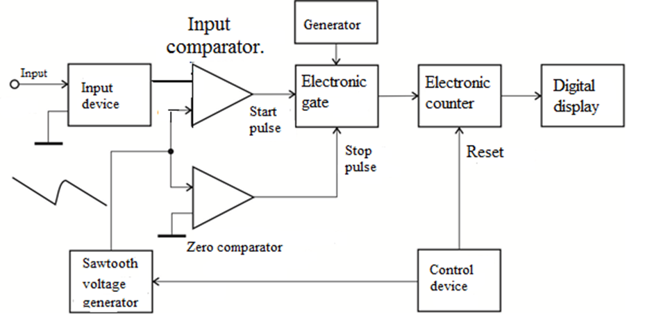
Figure 9
To measure an unknown voltage, it is fed to the input comparator. When the sawtooth voltages coexist with the unknown, the input comparator produces a starting pulse that allows the counting pulses to enter the counter. The "Stop" pulse is produced by the zero comparator when the sawtooth voltage becomes zero. From this point on, no pulses are sent to the counter. The result of the count is given in the visual indicator device (display) as a result of the measurement. At the end of the period, the counter is cleared and the linear sawtooth voltage is generated again, starting a new measuring cycle.
The accuracy of this type of voltmeter depends on the linearity of the sawtooth voltage and the sensitivity of the comparison devices. The sawtooth voltage generator and comparators often perform conversion with an accuracy of 0.01% of the full scale and a resolution of 10mV. The reading speed is of the order of several times per second.
Unfortunately, these voltmeters are not noise resistant. Assuming, for example, that the conversion is around the starting point, ie. the sawtooth voltage is almost equal to the input, then a noise pulse superimposed on the input voltage will cause premature activation of the input comparator.
In some types of voltmeters, the reset is performed by a pulse received from the trailing edge of the sawtooth voltage.
Apart from not being noise-resistant, this type of voltmeter cannot measure very low levels. This is due to the fact that parasitic mains voltages with a frequency of 50Hz at very sensitive bands have a strong influence on the measurement.
Starting pulses are produced from the zeroing pulses by delay . These pulses trigger the sawtooth voltage generator. The stop pulse, as already mentioned, is obtained by comparing the measured voltage with the sawtooth voltage.
Depending on the value of the measured voltage time for opening the electronic gate is determined. For example, voltage corresponds to time , voltage , time , and so on. During these times, pulses are fed to the electronic counter.
1.3.2 Digital voltmeter with code-pulse conversion.
The main conversion system of the voltmeter with code-pulse conversion produces a step-changing reference voltage, the steps of which correspond to the smallest order of the selected counting system.
The main block diagram of an electronic digital voltmeter realizing this conversion is presented in Fig. 10.
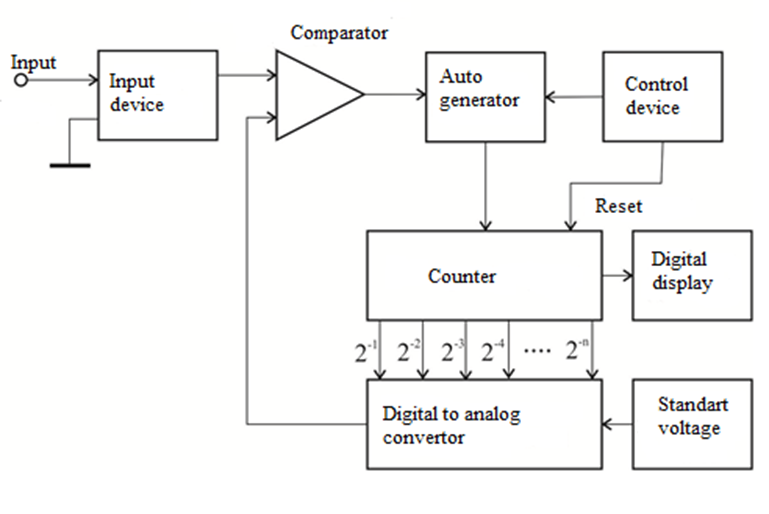
Figure 10
When the measurement starts, the starting pulse opens the gate and allows the counting pulses to enter the electronic counter and be counted. The output of the meter is connected to a digital-to-analog converter, the output voltage of which is proportional to its digital input. When each pulse enters the electronic counter, it is added to the last significant order and, accordingly, the output voltage of the digital-to-analog converter is increased by one significant step of the step-varying voltage. The input voltage is compared with the step-changing reference voltage. When the comparison device registers a draw the counter stops. The result of the count is proportional to the measured voltage and fed to the visual indicator device (display).
The performance of the voltmeter with code-pulse conversion is in many respects similar to the performance of the voltmeter with time-pulse conversion. A packet of superimposed noise will also cause errors. The accuracy of the measurement depends on the conversion accuracy of the digital-to-analog converter and on the stability of the internal reference voltage.
1.3.3 Digital voltmeter with continuous balance.
The continuous balance voltmeter uses parallel feedback to a digital-to-analog converter as a bit-coded voltmeter. When continuous balance voltmeter change it's voltage causes response to the feedback of the system that the measurement error is reduced.
Fig.11 shows the block diagram of the voltmeter with a continuous balance.
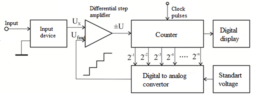
Figure 11
The operation of the scheme is as follows. If there is a positive difference between and , the differential and threshold amplifier produces (threshold voltage), which puts the addition-subtraction counter in the "summation" mode. Upon receipt of each clock pulse the summation is performed in the last value of the counter. The binary output signal is fed to the input of the digital-to-analog converter. When each bit is added output voltage of the digital-to-analog converter increases by the smallest discrete part of or by . When the feedback voltage approaches the value of the output voltage of the threshold device becomes less than and greater than . By this, zero balance is achieved and the sum-subtraction counter stops working.
The conversion time of a continuous balance voltmeter can be very large when changes from zero to the maximum range value. However, with small changes in , the conversion takes place in a very short period of time. The accuracy in voltmeter with bit coding depends on the stability of the reference voltage and on the accuracy of the digital-to-analog converter and the differential and threshold device. The accuracy of the conversion depends on its speed when frequency of the clock pulses increases the accuracy of the conversion decreases.
1.3.4 Integrating digital voltmeters.
Integrating digital voltmeters use two ways of converting voltage: converting voltage to frequency and converting voltage to time interval. In practice, the first types of voltmeters are often known as voltmeters with intermediate conversion of the measured voltage into frequency and the second type of voltmeters with double integration.
The basic principle of operation of a voltmeter of the first type is shown in Fig. 12. The applied voltage (with a positive value) at the input of the voltmeter causes a sawtooth voltage at the output of the integrator. When the sawtooth voltage reaches a preset value , the comparator switches on and activates the pulse generator. The pulse generator produces a rectangular pulse with a strictly defined duration and with an amplitude sufficient to restore the initial voltage level at the output of the integrator after which the integration process is repeated.
The slope of sawtooth voltage is proportional to the input voltage. A higher input voltage will increase the slope resulting in a shortening of the sawtooth voltage. Accordingly pulse repetition frequency will increase, because it is proportional to the input voltage therefore it is not difficult to count them in a certain time interval and obtain a numerical expression of the input voltage.
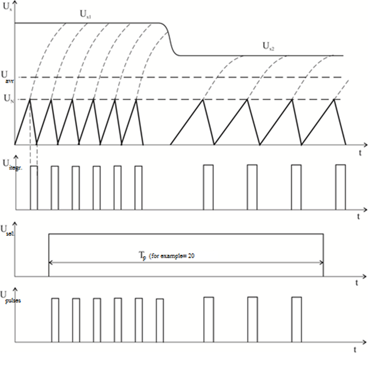
Figure 12
The accuracy of the integrating digital-to-analog converter depends mainly on the stability of the comparator, the amplifier and the capacitor. Typically, integrating voltmeters operate at fifty samples per second at a conversion accuracy of more than 0.01% of full range (Tp = 20ms). The block diagram of an integrating voltmeter with intermediate frequency conversion is shown in Fig.13.
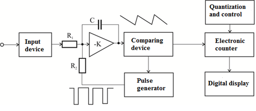
Figure 13
The biggest advantage of the integrating voltmeter is that it has the ability to "integrate" the input voltage over the measurement period. The reading represents the average value of the input voltage. The pulse repetition frequency "follows" the slow changes in the input voltage so closely that the changes in the input voltage are accurately reflected as a change in the pulse repetition frequency. In this way, noise is removed from the measurement without the use of input filters, which would increase the response time of the voltmeter. In addition, when the measuring interval is a multiple of the half-wavelength of the industrial voltage, the voltmeter acquires very important projector properties with respect to the hum from the power lines; this is a very valuable quality as these lines are a major source of disturbing noise.
Most modern electronic digital voltmeters use double-integrated ADCs, which have a number of advantages over other types of voltmeters.
The operation of the scheme is illustrated in Fig.14.
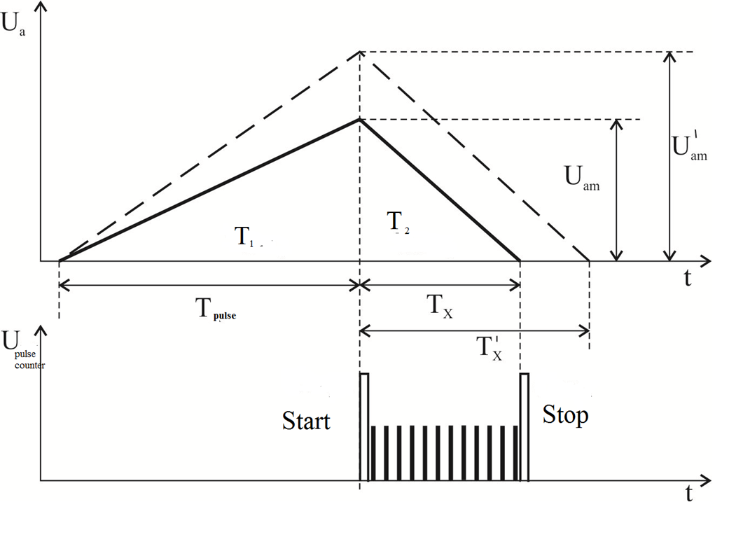
Figure 14
For the time (usually 20ms) when the switch is in position (1) the voltage of the integrator is:
In position (2) of the switch the voltage is:
Because and.
Thus integration method is a method for converting the measured voltage into a time interval. Fig.15 shows a block diagram of this type of voltmeters.
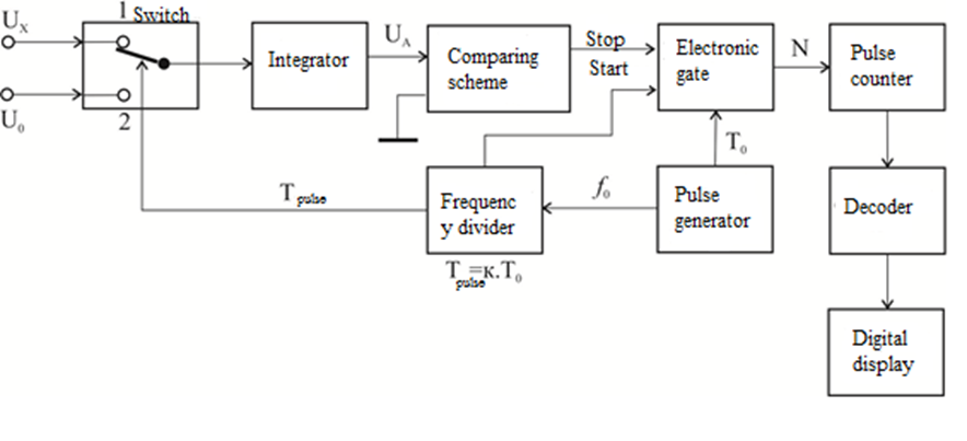
Figure 15
The pulse generator (PG) operates continuously. Clock signals are generated by the frequency divider (FD). The duration of the clock pulse is equal to half of its period . The clock pulse turns on the switch at position , where the position of the switch voltage is applied to the input of the integrator. At its entrance, its voltage changes according to the law:
At the moment the voltage . At the end of the clock pulse reaches the level , at which:
Here is the time constant of the integrator, and is the average value of for the time . The average value is determined by the expression:
As soon as the clock pulse disappears, the switch switches to position 2 and a reference voltage is applied to the input of the integrator. Its polarity is opposite to the polarity of and therefore the voltage at the output of the integrator will begin to decrease by law:
At the momen t (fig.14) the voltage becomes equal to zero. With the disappearance of the clock pulse, a starting pulse is formed for the door. When the voltage of the integrator becomes equal to zero, the measuring comparison circuit is activated and forms a pulse "Stop". The door was open for time . This time is determined by the number of pulses reaching the counter at and . It follows that:
In the above expression, substituting the value of we get:
Since ,
where is the division factor of the frequency divider, for we get:
The result of the measurement of is obtained after deciphering the state of the counter, as can be seen from the expression the double-integrating voltmeter measures the average value of the unknown voltage. If and , then the indication refers directly to .
Double-integrating voltmeters are very accurate (accuracy class 0.01 and even 0.001) for two reasons. First, their accuracy is determined only by the stability of , this stability can be very high regardless of the imperfection of the key, the integratorion scheme. The second reason is the averaging action of the integrator. The voltmeter get results almost independent of the interference that occurs with the unknown voltage.
1.3.5 Microprocessor digital voltmeters.
The new stage of development of digital voltmeters is related to their construction on the basis of microprocessor systems. Digital voltmeters made with microprocessor systems are devices with the ability to automatically switch the polarity and range of the measured voltage, statistical processing of measurement results and calibration. These devices are characterized by high metrological characteristics. For example, the relative error of such a voltmeter in the 10V range does not exceed 0.001% at direct current. The relative error in measuring the effective value of sinusoidal alternating current in the range of 100V does not exceed 0.03% for frequencies from 50Hz to 10kHz and remains less than 0.1% in the frequency range from 40V to 100V.
In the most general form, the block diagram of a microprocessor digital voltmeter is shown in Fig.16.
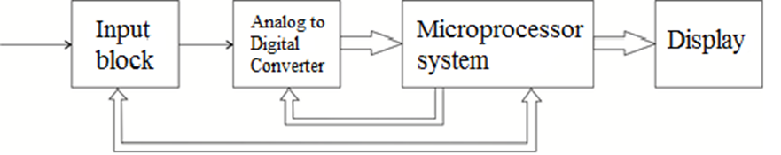
Figure 16
The input unit contains analog converters - attenuators and amplifiers. For some devices, this unit also includes a measuring transducer of AC to DC voltage (detector). These systems refer to cases where the speed of the microprocessor system is insufficient to calculate the RMS value of the measured voltage.
The design of microprocessor digital systems requires proper selection of ADC, appropriate microprocessor and their coordination. On the other hand, it is necessary to determine the main characteristics of the other modules of the microprocessor system and software development.
There are two possible options for organizing the coordination of the ADC with the microprocessor system.
In the first type microprocessor "perceives" the ADC as a cell in the system's memory. In this case, the number generated by the ADC output is sent to an address located in the field of addressed memory.
The second option is implemented when the system provides an "input-output" interface. The ADC outputs are connected to the inputs of the buffer, which is controlled by appropriate commands. In this case, a scheme is required to decrypt the signals in the microprocessor control bus and decrypt the buffer address.
One of the possible schemes for matching an eight-bit ADC and an eight-bit microprocessor is shown in Fig.17.
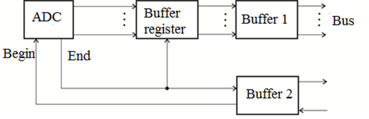
Figure 17
Two buffers are provided in the scheme. The first buffer is used in full and serves to enter the number formed at the output of the ADC, ie. of the data in the microprocessor system.
The second buffer is designed for control signals and is used in part - one bit at the input and output. At the command of the microprocessor, a single signal is applied to the output bus of buffer 2, which determines the beginning of the analog-to-digital conversion. A reversal to the input side of buffer 2 is then performed. The appearance of a single signal on the input line means the end of the analog-to-digital conversion. This signal "allows" the transmission of data from the buffer register via buffer 1 to the data bus.
The general view of the block diagram of a microprocessor digital voltmeter is shown in Fig.18. The microprocessor organizes the process of "measurement", controls the operation of all nodes, performs mathematical and logical operations with data coming from the ADC through an interface - data bus input.
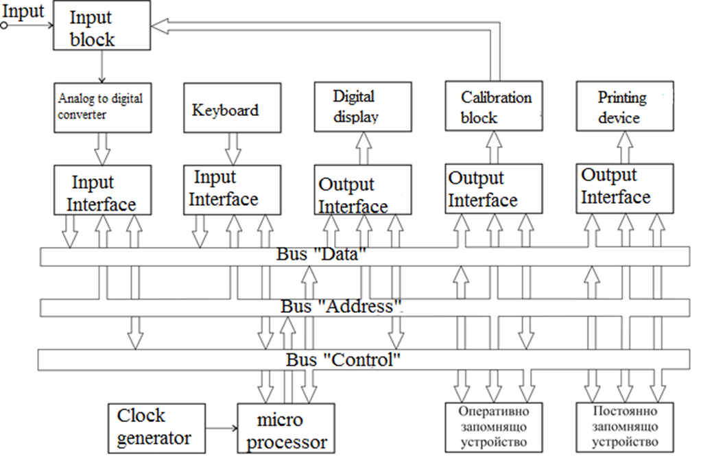
Figure 18
The program for operation of the microprocessor is stored in a block of permanent memory (ROM). This program is not deleted when the power is turned off. In this block some constants are entered, as well as some numerical data necessary for automatic calibration of the measurements. Measurement data is temporarily entered in the RAM block. The intermediate results of the measurements are also entered in this block. The connection between the microprocessor with the other modules and the exact interaction between the modules is realized through three buses: data bus, address bus and control bus.
The ADC and keyboard are connected to the buses via an input interface. The digital display, the printer and the auto calibration unit are connected to the buses via an output interface.
In addition to the ADC, the input devices include the keyboard. The keys can be grouped in logical blocks marked with inscriptions: type of measurement, operating mode, range, etc.
Many digital voltmeters can run several programs. They have a common "Program" key. When this key and the corresponding code number are activated, the respective version of the program is executed.
Лицензиран под Creative Commons Attribution Share Alike License 4.0