1-4. RF signal generators. Principles of building RF generators.
1. Definition, classification and basic parameters of measuring generators.
1.1. Definition.
Generator is an output device on which a reference calibrated sinusoidal signal is generated. It is generally the most commonly used device for checking and adjusting communication equipment. Depending on its type or field of application, there are different names such as: generator; measuring generator; sound frequency generator or functional generator. When the functional generator generates rectangular voltages it is called a pulse generator. The different categories of generators have the following features: the measuring generators have a calibrated attenuator and a built-in measuring device for the output voltage, the signal generators allow for modulation of the sinusoidal signal, and in the functional generators besides sinusoidal voltage non-sinusoidal voltages are generated (pulse, rectangular, triangular).
1.2. Classification.
The classification can be done in different ways. Two types classification can be made as follows:
A) Depending on the frequency range:
- Low frequency - 20Hz - 200kHz;
- Radio frequency - 20kHz - 30MHz;
- Video frequencies;
- High frequency;
- Ultrahigh frequency.
B) Depending on the principle of operation:
- Feedback generators;
- Beating generators;
- Functional generators (pulse generators);
- Negative resistance generators.
Other classifications can be made. For example, feedback generators are divided into RC generators; LC generators and quartz generators.
1.3. Parameters.
The parameters of the generators are mainly divided into primary and secondary, which will be considered separately.
A) Primary parameters.
The main parameters of the generators are five in number: frequency range; frequency stability; output power (output voltage); amplitude stability; nonlinear distortions.
Frequency range. This is the main parameter of the generators. On this basis, there are different types of generators that provide any desired frequency range. The low frequency generators have a frequency range from 20Hz to 200kHz. On the other hand, LC generators have a narrower frequency range, but work better at frequencies above 1MHz. The entire frequency range can be divided into individual subbands in order to smoothly tune the respective frequency.
Frequency stability. Frequency stability is expressed in the ability of the generator to maintain a constant selected frequency for a certain period of time. Stability is affected by changes in element values, supply voltages, operating conditions (temperature, humidity), vibration of the equipment. RC generators have the least stability, and to some extent the Robinson-Wien bridge circuit is more stable than the chain circuit. Stability is usually given as a percentage of the operating frequency, but sometimes is used the absolute deviation in hertz. Different values for frequency stability are given in the reference books. It can be set as stability under the influence of external destabilizing factors. The difference in frequency stability data in the reference books should be carefully compared and the destabilizing factors taken into account. In cases where the generator is quartz stabilized or has an automatic frequency control (AFC) circuit, the determination of stability is performed without switching off these additional devices. Therefore, stability data are higher and cannot be achieved with a basic generator alone. Quartz stabilized generators are undoubtedly with the highest frequency stability. Usually their stability is about 10.10-6 Hz or 0.01% for temperature change from 0° to 60° C.
Output power. The magnitude of the output voltage or output power that a generator can deliver on a given load is a basic parameter that is often misunderstood because there are different formulations. The classical method for defining maximum output power requires equality between the resistance of the generator and the load (operation of a matched load), which is often impossible or undesirable. The parameters of RC generators are often given at an output resistance of 600 Ω, while LC-generators usually have an output resistance of 75 Ω or 50 Ω due to the wider frequency range. Typical parameters of the generators are:
- 1W or 24.5V on a load of 600 Ω;
- 3W or 42.5V on a load of 600 Ω;
- 1W or 7.1V on a load of 50 Ω.
For some generators, only the output characteristics for reactive (inductive or capacitive) nature of the load are given. In such cases, it is necessary to refer to the operating instructions for the appliance.
Amplitude stability. The ability of a generator to keep its output amplitude constant for a certain period of time when the external conditions or signal frequency changes is called amplitude stability. Often this parameter is covered by the amplitude accuracy parameter, which includes the inaccuracy of the attenuator. RC generators with Wien-bridge have high amplitude stability compared to LC generators and chain RC generators. The factors that affect the stability of the amplitude are: the change in temperature; the change in frequency; the change in mains voltage. To maintain a constant amplitude, additional automatic gain control (AGC) circuits are included.
Nonlinear distortions. The presence in the output signal of the generator of components with a frequency other than the frequency specified by the tuning controllers is called nonlinear distortion. There are two types of nonlinear distortions: harmonic, the frequency of which is а number divisible by the fundamental frequency; noise, the frequency of which is not related to the fundamental frequency. The hum is a special case of noise nonlinear distortions with a frequency а number divisible by the frequency of the mains supply 50Hz. Nonlinear distortions are undesirable because the harmonic components in the output signal can be perceived by the studied circuit as the fundamental frequency. When a generator is used to measure the nonlinear distortions of a circuit, its own distortions need to be much smaller than those of the circuit under study. Harmonic distortions usually occur when the generator is operating in a non-linear mode for a certain part of the period of the generated oscillation and they increase with increasing frequency. With a relatively large output amplitude of the generator, the noise and hum are usually negligible, as their value is determined by the output amplifiers and does not depend on the amplitude of the signal. At low output amplitudes, noise and hum can represent a significant part of the total output signal. Usually the nonlinear distortions are given in the same units as the output value of the generator. If the output power or voltage is given in decibels, then the distortions are also in decibels.
B) Secondary parameters.
Attenuation and accuracy. The presence of a calibrated attenuator to select the maximum output amplitude greatly increases the suitability of the generator for some types of measurements. Most often, the steps of the attenuator are plotted in decibels or volts as well as the nominal power values. The steps are usually in 1dB or 10dB when the output value is power and in 20dB when it is voltage. The accuracy of the calibrated attenuator is given as a percentage or as a partial deviation from a set value. Often this parameter includes the stability of the amplitude of the generator for a long period of time something that cannot always be determined by technical data.
Symmetrical and asymmetrical output. The main generator circuits have an asymmetrical output (one end is connected to ground). Symmetrical output generators have a differential input in which one terminal is both positive for ground and the other negative. This is especially important as the output is floating and can be connected to any load without taking into account its ground potential. Some generators provide the possibility to select one of the two types of outputs, and sometimes two or more output resistors for each of them, for example asymmetric output: 50 Ω and 75 Ω; and symmetrical output: 135 Ω, 150 Ω, and 600 Ω.
Irregularity of the frequency response. The irregularity of the frequency response indicates how much the output level of the generator remains constant throughout the frequency range. The unevenness varies widely for different types of generators. In some cases, it is considered as part of the already considered parameter "amplitude stability".
Frequency accuracy. The frequency accuracy parameter gives the largest deviation of the actual output frequency of the generator from that read on the tuning scale (or tuning buttons). This usually includes all the reasons for the frequency deviation, such as the influence of external conditions, the parallax of the frequency tuning mechanism, the frequency stability and the tolerance of the attenuator elements. A typical value of frequency accuracy for RC generators is ± 2%, and for LC generators is ± 1%. Sometimes the frequency accuracy parameter is found under other names, such as the accuracy of the frequency tuning scale or the accuracy of the calibration.
Amplitude, frequency and pulse modulation. Generators in which the signal can be modulated to mimic real signals used to transmit messages are called signal generators.
Usually three types of modulations are performed with them: amplitude, frequency and pulse.
Amplitude modulation is most often performed by a built-in tone generator with a frequency of 1kHz. The possible depth of modulation for different signal generators varies widely (from <30% to <95%). With many generators, external modulation with a frequency from 0 to 20kHz is also possible.
Frequency modulation is described in a similar way. Usually the frequency deviation is 75kHz with modulation distortions below 1%. In the case of high-quality generators, the range of modulation, calibration, nonlinearity and parasitic frequency modulation is given.
Pulse modulation is usually performed from an external source. The duration of the leading and trailing edges and the depth of modulation in decibels are always given in the parameters of the generator.
Output voltage meter. A significant number of generators have a built-in analog voltmeter, which serves as a measuring device for the output signal. Typically, the voltmeter measures the actual output signal of the generator after the output amplitude regulator, but before the calibrated attenuator. In the case of sinusoidal voltage generators, the meter is set to an effective value. In the case of pulse generators, it takes into account the maximum value of the signal.
2. Low frequency generators.
As the frequency decreases, the inductance and capacitance of the elements in the resonant systems of LC-generators increase significantly. This leads to an increase in the size of the coils and capacitors, in addition to increasing the active losses in these elements and reducing the quality factor of the circuit. This reduces the frequency stability of the generator. For this reason, generators in which the oscillating system is composed of RC elements have found main application in the range below 200kHz. There are three main ways to implement RC generators:
- Chain generators (with phase rotating group);
- Generators with Wien bridge;
- Generators with RC-filter in the negative feedback.
The block diagrams of all RC measuring generators are
analogous and have the type shown in Fig.1.
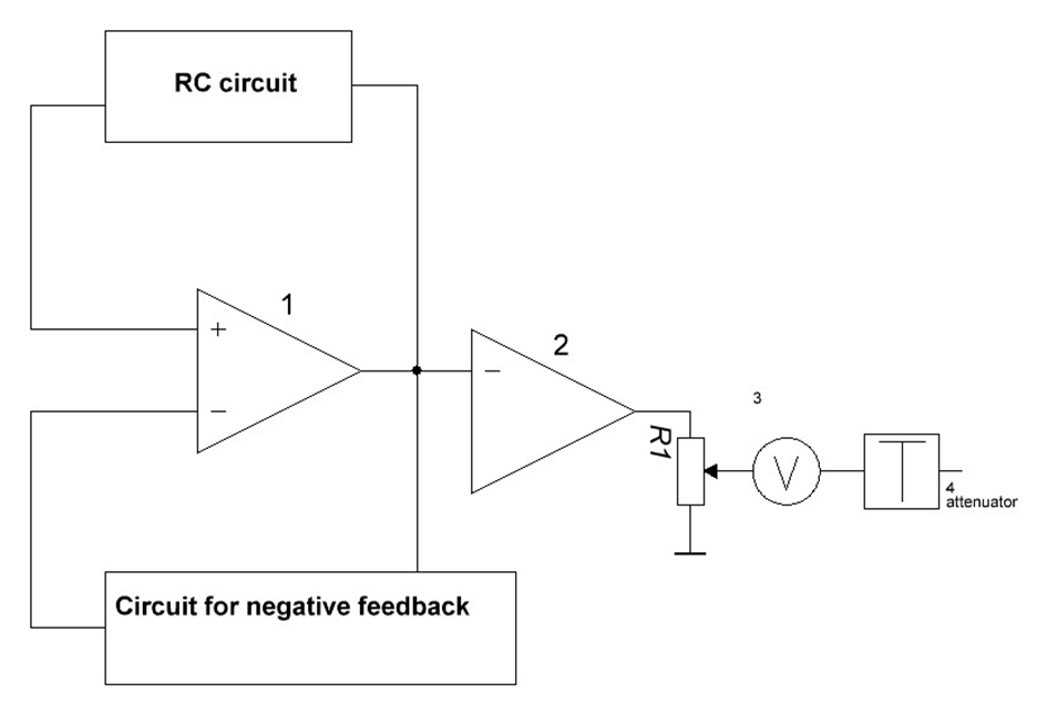
Fig. 1
The main elements in the block diagram are:
1. Pilot oscillator;
2. Amplifier;
3. Electronic voltmeter;
4. Attenuator.
The amplifier of the pilot generator is covered by two feedback loops. The positive is realized through the frequency-dependent RC-circuit, and the negative - by the frequency-independent negative feedback.
A) RC chain generators.
Figure 2 shows the circuit of an RC generator of this type. It contains an amplifier K and a positive feedback circuit. This circuit is formed by several RC units. In order to fulfill the condition for amplitude balance, it is necessary for the amplifier to have a large gain K. In order to generate sinusoidal oscillations in the generator, the condition for phase balance must be fulfilled for only one frequency - the desired one.
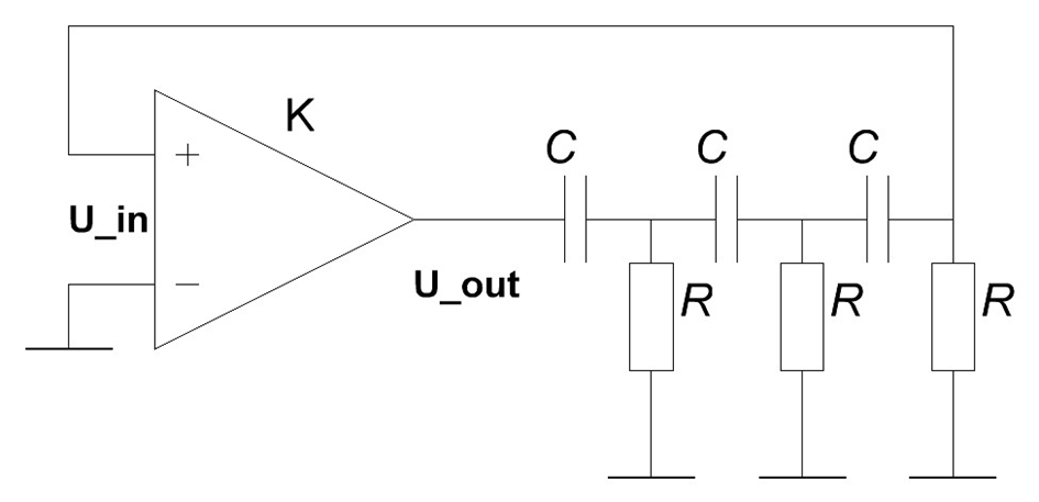
Fig. 2
An RC unit always dephases at an angle of less than 90°. Therefore, RC generators with phase rotating groups must contain at least three such RC units. For the three star groups, two main schemes "R parallel" and "C parallel" can be used (Fig. 3 a, b).
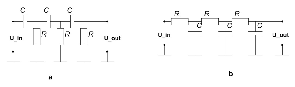
Fig. 3
The choice of identical RC units is dictated by considerations for easier calculation and construction of the scheme. The phase-shifting generator can be tuned by simultaneously changing the resistance of the resistors or the capacitance of the capacitors. Regulation is associated with great difficulties of a constructive nature. For this reason, these circuits find applications for fixed frequency generators.
B) RC generators with Wien bridge.
This type of generators has found the widest application in measuring technology. They have great possibilities for frequency regulation in a wide range with high frequency stability. The schematic diagram of the generator is shown in Fig. 4.
The two RC groups (connected in parallel and in series) together with resistors R1 and R2 form the so-called Wien Bridge. In one diagonal of the bridge is connected the output of the amplifier, and in the other diagonal the input of the amplifier. Positive feedback is performed by both RC groups and it is frequency dependent feedback. It fulfills the phase balance condition for the desired frequency. A frequency independent Negative feedback is introduced via resistors R3 and R4. This Negative feedback establishes the operation of the amplifier in its linear part of the characteristic, which achieves high stability of the generated frequency and the lack of harmonic components in the output signal.
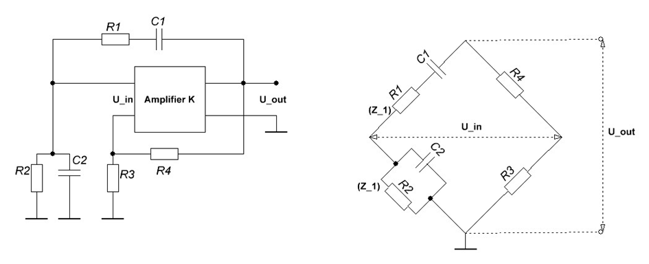
Fig. 4
The tuning of the generator to the required frequency is done by simultaneously adjusting the two capacitors C1, C2 or the two resistors R1 and R2 from the bridge. The switching of the individual ranges is done by changing the values of the elements. In practice, the method of frequency regulation through resistors has applied, but in this case the scale of the generator is uneven. The capacitors and resistors of the Wien bridge must be stable, and the capacitor must have small losses, because otherwise the phase ratios in the circuit change. If the generator must be powerful then the generated oscillations are fed to a powerful output amplifier. The output of the measuring generators is always connected with an attenuator. An electronic voltmeter is connected in front of the attenuator to monitor the output level of the generator.
C) Beat generators.
This type of generators is widely used in the low frequency and video range. The block diagram of such a generator is shown in Fig. 5.
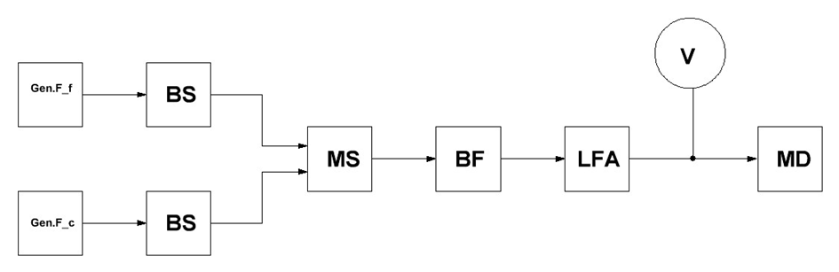
Fig. 5.
The following designations are entered on the block diagram: Gen. Ff and Gen.Fc are high frequency sinusoidal voltage generators; BS - buffer stage; MS - Mixer stage; BF - band filter; LFA - LF amplifier; V - voltmeter for indication; MD - matching device. One of the generators is set to a fixed frequency Ff (120kHz), and the other has a continuous varying frequency within certain limits Fc (100 to 120kHz).
The buffer stages serve to separate the two generators and eliminate their mutual influence. In the mixer, the difference between the two frequencies is obtained. The frequency of the two generators is stabilized parametrically and special measures are taken to stabilize their amplitude. Due to the possibility of zero beating in these generators, scale calibration by frequency is easily achieved. The mixer can be any of the known frequency converters, but in view of the specific features and requirements in this case the most suitable is the circular modulator. A variant of such a modulator is shown in Fig. 6.
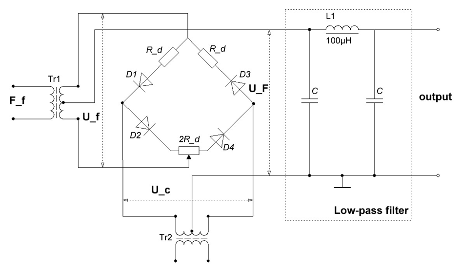
Fig. 6
This type of modulator has the highest conversion factor and relatively low nonlinear distortion. It suppresses the two high frequencies very well and thus improves the filtering of the LF voltage UF. Another advantage of the shown circuit is the lack of a transformer in the output of the modulator. The low pass filter is usually two to three "k" type units. It is necessary to shield the two generators to eliminate any parasitic connection between them.
Characteristic features of this type of generator are:
- Wide frequency range (without switching subbands);
- Good frequency response.
The main disadvantages of the generator can be pointed out:
- The relatively complex circuit solution;
- Higher price compared to RC generators.
For these reasons, in recent years, RC generators have become more widely used for low-frequency measurements in communication technology.
3. High frequency and Ultra high frequency measuring generators.
3.1. Classification and basic parameters.
As this is a very wide class of devices it is present consideration, the high-frequency generator is considered to be an alternating current energy source having most of the following parameters:
1) Output signal with calibrated frequency, the value of which can be changed;
2) Calibrated output voltage, the value of which can be
changes;
3) Ability to modulate the output signal.
In measurements in communication technology, this type of generators is in most cases called signal generators.
The output signal of a signal generator is called modulated if its amplitude or frequency changes in accordance with some modulating signal. Two types of generators will be considered:
- Signal generator with amplitude-modulated signal;
- Signal generator with frequency modulated signal.
In principle, the structural scheme of a high-frequency generator and a microwave generator is the same. There are differences only in the circuit and design solutions of the individual units (master generators, modulators, attenuators, etc.).
The main purpose of measuring RF and microwave generators is to measure the sensitivity of radios in this range, power antennas with microwave energy, measuring lines, reflectometers and other measuring systems, as well as power supply in the study of traveling wave lamps, in the study of the characteristics of the environment and substances, etc. The functional diagram of the generators of this type is shown in Fig. 7.
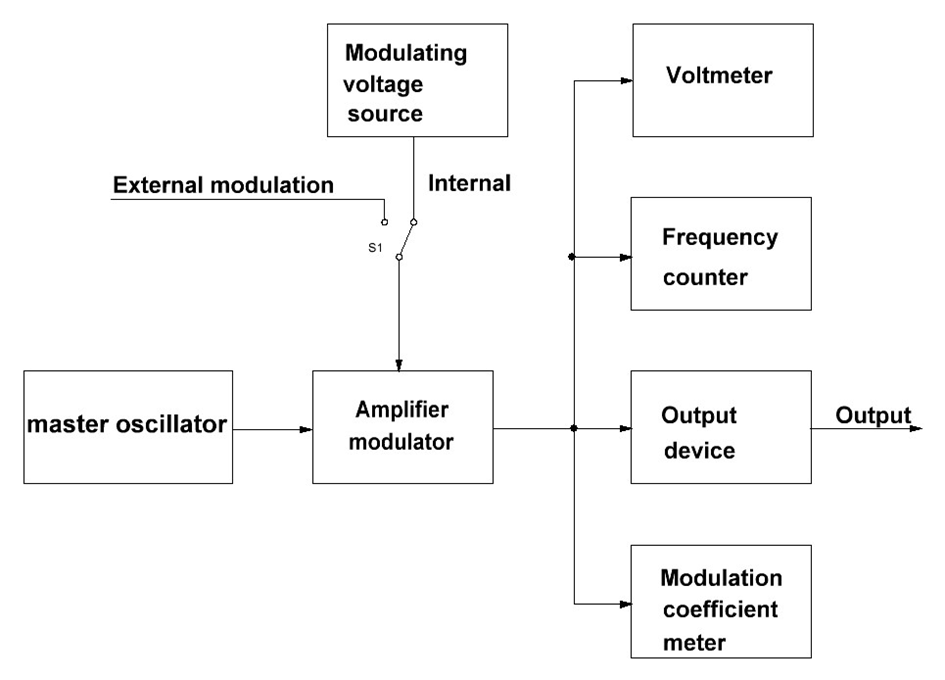
Fig. 7
The master oscillator is the main device of the measuring generator of the microwave range and determines its main characteristics, including the characteristics of the output signals. Not only the level of the output power and the frequency range depend on the master generator, but also a number of parameters and characteristics of the modulated signals - duration and repetition period in pulse modulation, frequency deviation in frequency modulation.
The master generators use klystrons, lamp triodes, semiconductor integrated circuits, traveling wave lamps and other devices with the ability to work in a wide frequency range and electronic tuning of the frequency.
Klystron master generators operate in the high frequency part of the decimeter, centimeter and millimeter range. For signal generation with a frequency lower than 7500MHz, reflective klystrons with an external coaxial resonator plugged between the klystron disk terminals are used.
The adjustment is performed by changing the volume of the resonator mechanically. For frequencies above 7500MHz, reflective klystrons with volumetric resonators built into the balloon itself are used. The mechanical readjustment of klystron allows you to change the frequency up to 30% and electronic tuning up to 1% - 2%. Usually in klystron generators simultaneously with the mechanical adjustment of the resonator is applied by means of a special kinematic scheme and automatic change of the voltage of the reflector.
When operating klystron generators who operate in a wide frequency range, it must be borne in mind that their power does not remain constant throughout the frequency range, unless special stabilization measures are taken. The power reduction in the range is different for different types of klystrons.
To increase the stability of the frequency of the generated oscillations, the supply circuits of the anode of the klystron reflector with a high stabilization coefficient are stabilized, and the heating circuit - by maintaining of constant heating current. The solution of the problem of rational power supply of klystron generators from centimeter range is not difficult, but for klystrons from millimeter range there are difficulties due to the need to use high-voltage rectifiers and due to the steepness of electronic frequency adjustment depending on the voltage of the klystron reflector - often over 2MHz / V.
Master generators filled with tube triodes are used for frequencies up to (8-10) GHz. Electronic lamps in this case must have a special construction - most often metal-ceramic with disc terminals. These generators have a number of advantages over klystron generators:
- Operation at lower supply voltages;
- No less number of power sources are needed;
- They are characterized by higher frequency stability;
- A good separation between the generator and the load can take place;
- Amplitude modulation is easily performed without significant parasitic frequency modulation, etc.
- A disadvantage of generators of this type is the difficult frequency tuning.
Depending on the type of triode used given in the load maximum power can be from a few tens of mW to a few watts.