EXAMINATION OF SIGNAL GENERATORS
The purpose of this laboratory exercise is to enhance the skills of learners to check the metrological characteristics of signal generators, to examine the internal resistance, amplitude-frequency characteristics, accuracy of outgoing signals’ parameters and also acquiring practical skills for equipment exploitation.
1. Theoretical introduction.
The signal generators, used for measurement, present sources of different electrical and electromagnetic waveforms with the possibility to alter the frequency, amplitude and power to some limitations. These limitations define the equipment’s capabilities, and the Class of accuracy define the metrological characteristics.
The most important signal generator parameters, used for measurements, are:
- frequency range – this is the frequency interval fmin - fmax , in which the outgoing signal follows all requirements of accuracy;
- carrier frequency error – depends of frequency stability during duty intervals. The absolute carrier frequency error is presented by:
where is the absolute methodical scale grading error, and ε represents the main relative error in the working frequency interval. Common values are: ε=0,1÷3% and ferr =1÷3 Hz;
- frequency deviation – this is the relative instability of carrier frequency. It is described with δ as:
.
Factors, affecting frequency destabilization are changes of environment temperature, alternations in power supply, humidity, etc. The relative frequency instability for a time interval is presented by:
where f2 and f1 are respectively the maximum and the minimum measured frequencies;
- amplitude stability – this is the capability of a generator to maintain the amplitude of the outgoing signal in a constant value for interval of time, despite the changes in environment. Factors affecting amplitude stability are: changes in temperature, changes in frequency, power supply instabilities. Automatic gain control (AGC) solutions are applied for improving the amplitude stability in some cases;
- nonlinear distortions – those are frequency components in the outgoing signal that are not part of the input. There are two main types of nonlinear distortions: harmonic distortions and noise distortions. The brum is part of the noise distortions, which is activated by the 50HZ power supply AC-current frequency.
2. Practice tasks and instructions.
Task 2.1: Learn the connection circuit, working principles and the control and regulation of the signal generator used for measurement.
Students are obligatory to learn the theoretical aspects before performing the practice tasks. On fig. 1 the connection circuit for examination of signal generators is depicted.
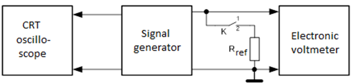
Fig. 1 – Connection circuit
The connection circuit should contain the following equipment:
- signal generators used for examination – 5 pcs.;
- cathode ray tube (CRT) oscilloscope – 1 pc.;
- electric voltmeter – 1 pc.;
- electronic voltmeter – 1 pc.;
- digital frequency counter – 1 pc.;
- standard reference resistance (Rref = 1,5kΩ);
- high-frequency connecting cables – 3 pcs.;
- interconnecting triple – 1 pc.
Task 2.2: Measure the output resistance Rout of the generator.
The output resistance Rout of a signal generator is a parameter equivalent to its power payload. To perform the measure of the output resistance, a switch box with a reference resistance is used.
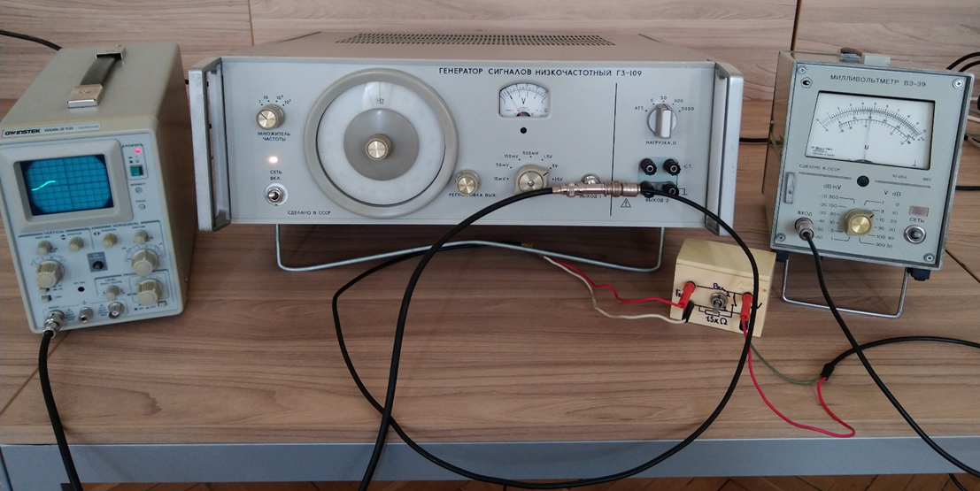
Fig. 2 - Connected devices image
With the switchbox key pointing to position 1 the outgoing voltage of the generator U1=U=Egen is measured by the voltmeter, which has sufficient ingoing resistance. After this measure, the generator is loaded with the reference resistance Rref by switching the key to position 2 and the outgoing voltage U2 = I.Rref is measured. For the key in position 2 it can be written:
Еgen=I.(Rout + Rref )
Using the mentioned equations, for the output resistance of the generator we have:
Usually, the outgoing resistance is in the range of kiloohms. The measured values of the two voltages U1 and U2 should be written in Table 1, after which, the signal generator output resistance Rout is manually calculated. The frequency, in which the values are measured, should be in the middle of its subrange.
Task 2.3: Define the error in the frequency scale when setting up the work frequency.
Frequency error check is done by the means of direct measurement with digital reference frequency counter. The frequency counter is caught to the output of the signal generator. The frequency error check is performed:
- in generators with subranges, containing more than 3 frequencies;
- in generators without frequency subranges, to more than 5 equally distributed frequencies similar to 10, 20, 50, 100, 200, 500 Hz; 1, 5, 10, 20, 50, 100, 200, 500 kHz; 1,5,10, 20, 50, 100, 200, 500 MHz;
- in generators with decad scale – at least 3 points for each decad, usually it is the start, middle and end of decad.
In generators, working with the principle of sound adjust, the settings should be done prior frequency error check. The absolute frequency error Δf measured in Hertz, and relative error δf measured in percentage, for the main scale, are calculated by the formula:
fnom – the nominal value set for the signal generator frequency;
f0 – the frequency, measured with the reference frequency counter when the settings switch is set to 0.
The obtained measurement results should be written in Table 2.
Task 2.4: Define the error in the value of the generator output voltage while setting the output signal amplitude.
The error of output voltage amplitude is checked with reference voltmeter while attenuator is turned off, and generator payload is equivalent to its technical documentation sheet, mostly 50Ω. If the scale is one row (voltage or decibels), this check is performed for more than 5, digit-labelled, points. This is done while frequency is fixed. If the scale is multi-row, the check should be performed for more than 5, digit-labelled, points for each scale row. The obtained measurement results should be written in Table 3.
To define the accuracy of output voltage in the embedded measurement system, the relative error should be calculated by the formula:
where: Unom – the voltage nominal value, set according to the reference scale;
U0 – the voltage value measured by the reference voltmeter;
Uend – voltage value of the last digit-labelled point in the scale row
Task 2.5: Plotting the frequency to voltage relevancy.
For task 2.5., the amplitude-frequency domain should be plotted. The amplitude-frequency domain characteristics describe whether the generator is able to maintain constant amplitude (constant signal level) when frequency is altered. The amplitude-frequency characteristics are taken by setting a constant voltage value of the output signal and frequency alternation on equal points for each subrange. The obtained measurement results should be written in Table 4.
Task 2.6: Report writing containing the performed measurements.
Students have to create a written report and draw graphics using data in tables 1÷4. The reports should contain conclusions for all tasks.
3. Control questions:
3.1. What are the technical requirements for signal generators used for measurement?
3.2. Point some generator output devices used for different frequency ranges?
3.3. Are you able to draw basic LC generator circuits?
Images of used devices:
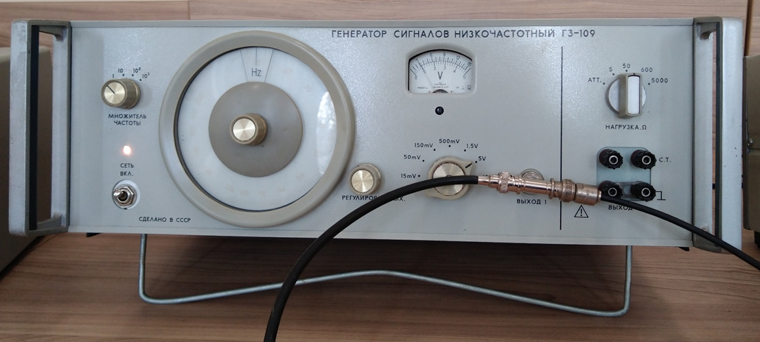
„ГЗ-109“ low frequency signal generator
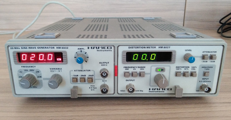
„Hameg Instruments HM8032“ signal generator
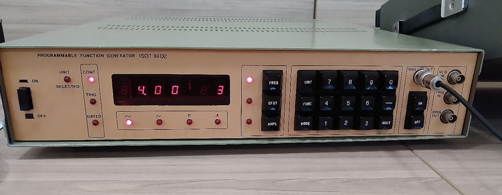
„ISOT 9202“ programmable function generator
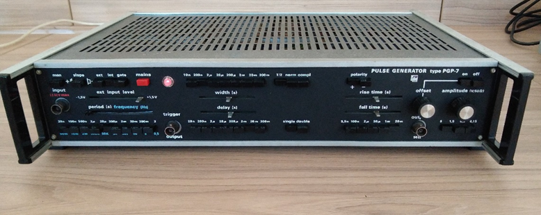
„Kabid PGP-7“ pulse generator
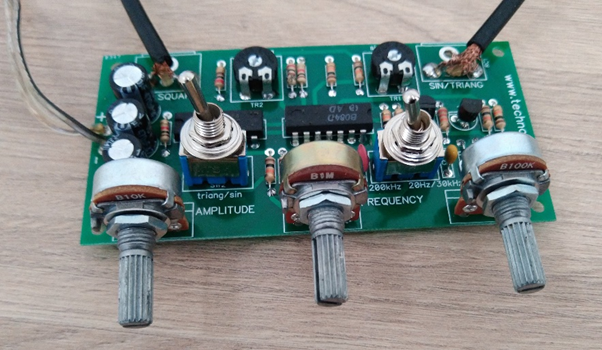
Hobby kit signal generator
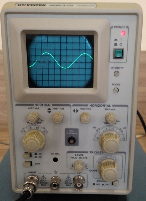
„Instek GOS-310“ Cathode ray tube (CRT) oscilloscope
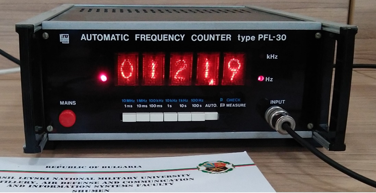
„PFL-30“ vacuum tube frequency counter
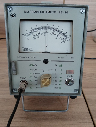
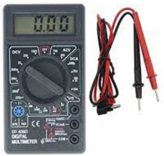
Electric voltmeter Electronic digital multimeter
High-frequency connecting cables – 3 pcs.:
Interconnecting triple
Standard reference resistance (Rref = 1,5kΩ) with switch key