Measurement of power and current at high and ultrahigh frequencies. Features of measuring high frequency currents.
1 Measurement of current and power at medium, high and high frequencies.
1.1 Features of current measurement.
Currents in industry can often be measured directly with electromagnetic and electrodynamic ammeters. Electrodynamic ammeters are characterized by greater accuracy. The measuring range of the electromagnetic ammeter is extended by changing the number and diameter of the windings of the windings of its coil or by using shunts. The applications to extend the range for measuring currents at low often find current transformers. As the frequency of current measurement increases, the accuracy of electromagnetic and electrodynamic ammeters decreases sharply. At high frequencies their use is impossible due to the reactive nature of their internal resistance and the increasing influence on the parasitic capacitance.
The equivalent circuit of an ammeter (regardless of its type) in the high ones often has the form shown in Fig.1. According to the scheme, RA denotes the internal active resistance of the ammeter with LA and CA own parasitic inductance and parasitic capacitance of the ammeter; Cp1 and Cp2 - the parasitic capacitances of terminals 1 and 2 relative to ground.
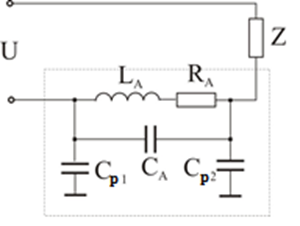
Fig.1
The equivalent circuit shows that the total resistance of the ammeter is complex and depends on the frequency, therefore:
1) with the increase of the frequency of the reactance of the device does not increase and this influence on the value of the measured current;
2) the parasitic reactive elements determine the natural resonant frequency of the ammeter, which is as high as these elements have smaller values. If the measurement frequency is equal to or close to the resonant frequency of the ammeter, the measurement mode of the circuit will be severely disturbed and the measured current value will differ significantly from the actual value.
To measure current at high currents, it is often recommended to include an ammeter in lower potential circuits. In this case the shunting of the parasitic capacitances is reduced (Fig.2).
The higher the frequency of current measurement, it is more difficult to create an ammeter that meets these requirements. Therefore, measuring current with a frequency higher than, for example, 3GHz is not possible. The estimation of currents with such currents is often done indirectly by determining more accessible for measurement quantities such as voltage, power, field strength, etc.
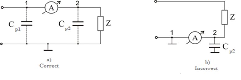
Fig.2
Ammeters based on the conversion of alternating current into direct current are most often used to measure alternating currents over a wide frequency range. These are:
1) ammeters with detectors for average value;
2) thermoelectric ammeters;
3) electrodynamic;
4) photoelectric;
5) ammeters with conversion of current into voltage on reference resistance.
1.1.1 Ammeters with average detectors.
Rectifier ammeters convert alternating current to direct current. Average detectors are used, which have already been considered. The frequency range of the rectifier ammeters depends mainly on the own capacity of the rectifiers and on the availability of frequency compensation. Ammeters with rectifiers without temperature and frequency compensation are used in the frequency range from (10-20) Hz to 10kHz, and with compensation - up to (2-3) GHz. Germanium and silicon diodes extend the frequency range to 100MHz and for rough measurements (as indicators) - to (1-3) GHz. The voltage drop in the rectifier ammeters ranges from 0.5V to 1V.
The advantages of rectifier ammeters are:
- High current sensitivity;
- Low power consumption;
- Small dimensions;
- Wide frequency range.
The disadvantages of this type of ammeter are:
- The dependence of Zpr and Robr of the diodes on the temperature;
- Nonlinearity of the scale (concise at the beginning);
- Low accuracy (accuracy class 4; 2.5 or 1.5);
- Dependence of the reading on the shape of the measured current.
1.1.2 Thermoelectric ammeters.
Thermoelectric ammeters are based on the thermoelectric effect, which is expressed in the conversion of the measured alternating current into a constant thermoelectric voltage. They consist of a thermocouple and a magnetoelectric measuring mechanism usually a voltmeter.
These are some of the most common types of ammeters when measuring high frequency currents used to measure current up to 1A. The thermocouple itself consists either of a thermocouple - two conductors of different material connected at one point or of a thermocouple (CD) and a heater (AB). There are three schemes of thermocouples) (Fig.3). Fig. 3a) and the shunt thermocouple (Fig. 3b) the measured current flows through the thermocouple and heats the thermocontact with high specific resistance - nichrome, constantan, etc.), which heats the thermal contact.These thermal converters are contact and non-contact, which are indirectly heated.
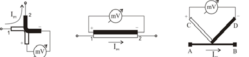
a) b) c)
Fig.3
Under the action of the heat released by the measured current, the thermocontact (hot solder) of the thermocouple is heated, and a thermo-viltage occurs at the cold ends. It is proportional to the temperature difference between the hot solder and the cold ends of the thermocouple, ie. of the heating temperature (T).
Due to the thermal inertia, the increase in temperature T is proportional to the square of the measured current I, where for Et we get:
where: RI is the resistance of the measureing mechanism taking into account the resistance of the thermocouple K1, K2 - coefficients of proportionality, depending respectively on the properties of the thermocouple and the measureing mechanism data.
Since the measured current is squared in the expression, the ammeter can be used to measure direct and alternating current. Its scale is graduated in effective current values and has a quadratic character.
Fig. 4 shows the construction of a contact type thermocouple.
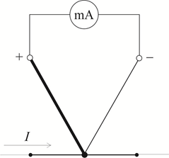
Fig.4
`In non-contact thermocouples, the heater and the thermocouple are insulated from each other by a glass bead, which impairs heat transfer, increases heat inertia, reduces sensitivity, but allows several thermocouples to be connected in series (Fig. 5).
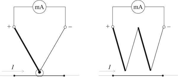
Fig.5
In addition, the advantage of the non-contact thermocouple is the absence of a galvanic connection between the magnetoelectric measureing mechanism and the circuit of the measured current. The capacitive connection between them is weak (the capacitance between the heater and the thermocouple is very small - of the order of 0.5pF), which significantly reduces the influence of the parasitic capacitance of the measureing mechanism on the accuracy of measuring high frequency currents. Therefore, at frequencies higher than 10MHz, thermocouples with indirect heating are generally used. To increase the sensitivity and for more efficient use of thermo - voltage. the thermocouples are connected in a bridge circuit (Fig.6) in the diagonal on which the measureing mechanism is connected. The arms of the bridge consist of thermocouples, which are so connected that thermo – induction voltage. to be summed.
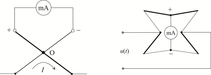
Fig.6
Depending on the type of thermocouple, thermoelectric ammeters are used to measure direct and alternating current in the frequency range from 50Hz to 200MHz. Their accuracy class is from 1 to 4.
The main purpose of thermoelectric ammeters is to measure high frequency currents. At high frequencies, the parasitic parameters of the thermocouple and the surface effect of the heater appear. This leads to the appearance of frequency errors, the value of which depends on many factors, including the design of the thermocouple and the value of the measured current. For example, when measuring currents up to 100mA using 6-pin converters, this error is insignificant for frequencies up to 1GHz, but it increases strongly in high current meters. Therefore, each ammeter is designed to operate for a specific upper cutoff frequency. Fig.7 shows possible constructions of thermocouples.
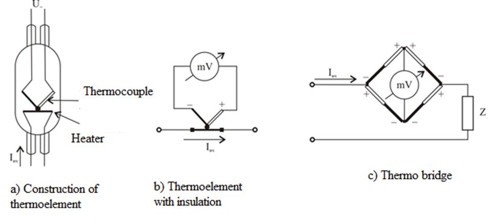
Fig.7
Thermoelectric ammeters measure currents in a wide range - from 100μA to tens of amperes. Vacuum thermocouples are used to measure small currents up to 500mA, and air thermocouples with radiators are used to measure currents from 500mA to 50A. Because the heater usually operates in a state close to the point of redness, it can not withstand a large overload - up to 50%. Otherwise there is a risk of overheating, deformation or burns. Therefore, when operating thermoelectric ammeters, not only their overload must be avoided, but also the passage of short-term current pulses, such as capacitor charge, etc.
Photo amplifiers are used in thermoelectric ammeters to amplify the direct current of thermocouples. Ammeters with photo amplifiers have increased resistance to overload, high sensitivity and frequency range up to 1MHz.
The presence of harmonic components in the measured current causes a slight increase in the reading of the ammeter. At 20% the content of harmonic readings increases by 2%, and the phase ratios of the harmonics do not affect the reading.
The main disadvantages of thermoelectric ammeters are:
- Do not allow even short-term overload;
- Small operating period of the thermocouple;
- Significant own power consumption.
The weak influence of the frequency and shape of the alternating current curve on the reading of thermoelectric ammeters determines the field of their application - the measurement of high frequency currents.
1.1.3 Photoelectric ammeters.
The photoelectric method used in photoammeters (Fig. 8) is based on the conversion of current into light. The measured current flows through the wire of lamp L and heats it to glow.
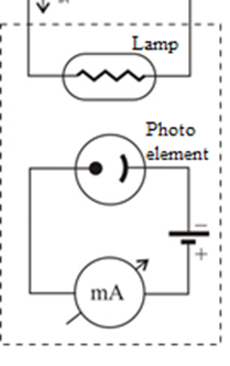
Figure 8
The constant photocurrent in a photosensitive element is a unique function of the measured alternating current. The measurement is usually performed by substitution, which sharply increases the accuracy: after taking the reading during the measured alternating current, a direct current of the magnitude causing the same deviation is passed in the circuit. The direct current is equal to the measured current and can be read with very high accuracy.
Due to their high accuracy, photoelectric ammeters are often used as reference. Another advantage of these ammeters is the low frequency dependence of the readings, which is due to the separation of the indication circuit from the high frequency current circuit.
The disadvantage of photoammeters is the very small dynamic range, which limits their applications.
1.1.4 Bolometric ammeters.
They are used for measuring low currents (below 1mA) with a very high frequency (in the range of decimeter and millimeter waves) and for insignificant consumption (up to 10-8W). Fig.8 shows the diagram of a bolometric ammeter.
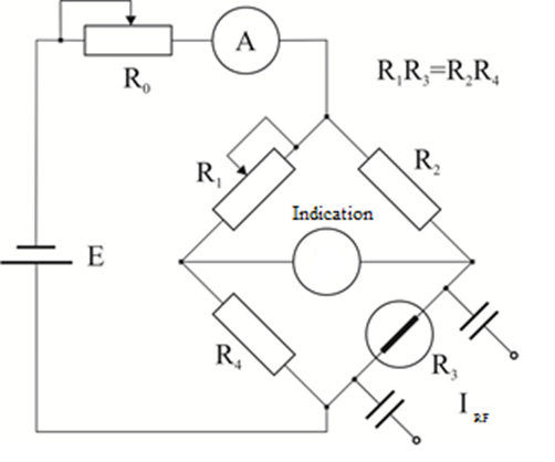
Figure 9
The main element in them is the so-called bolometer, which is a thermistor with a positive temperature coefficient. It consists of a thin (with a diameter of 1.5 - 15μm) tungsten or platinum wire (up to 8mm long), placed in a vacuum or filled with noble gas glass balloon. As can be seen from the figure, the bolometer is included in one arm of a DC bridge, which is pre-balanced (balanced) by means of resistor R1.
After the flow of the measured high-frequency current through the bolometer, its resistance increases, the bridge is unbalanced and the galvanometer gives an indication proportional to the change of the bolometric resistance R3.
The resistance of the bolometer varies approximately in quadratic dependence on the effective value of the measured current, therefore the scale of the instrument will be plotted in quadratic dependence.
1.2 Features of high frequency power measurement.
In communication technology, the range of power used is too large - from peak to tens of megawatts, and frequencies from sound to millimeter range. Therefore, the methods and means of measuring power are too diverse and relatively complex. There are mainly two cases of power measurement.
1. Power dissipated at any load having a complex resistance.
2. Power that can be obtained from a given energy source.
The first case is more complicated because the work has to be determined and is a difficult problem that cannot be solved with sufficient precision. The second, on the contrary, is solved more easily and precisely enough, since it is necessary to include a calibrated active resistance to the source and the multiplier is then absent in the power expression. This method is applied equally successfully for frequencies from direct current to the millimeter range.
It is accepted that the powers used in communication technology are divided into four groups: large powers - from 10W to 10MW and more; average power - from 0.1W to 10W; small powers - from 100mW to 10μW and too small powers - below 10μW. In many cases the powers are given in relative units of decibels, [dB] = 10lg (P / P0) relative to P0 = 1W or 1mW power, so that "positive" or "negative" power can be obtained depending on whether the power P is more greater than or less than P0. If P0 = 1W power expressed in decibels is selected as a relative unit, it is abbreviated as [dBW] in case P0 = 1mW then power expressed in decibels is denoted as dBmW or only dBm. This way of expressing the power is very convenient when transmitting power on a line where there is attenuation or amplification in the system. For example, the power level diagram of a radio relay line, which indicates the power in the transmitters, feeders, antennas, free space, etc.
The choice of the power meter to be used in specific measurements should be based on several parameters, including the frequency of the electrical signal, the expected value of the power, the shape of the measured signal, the degree of accuracy required for measurement and this , whether the power of the energy source or the power on the load will be measured.
This wide range of requirements is met by one or another type of devices designed to measure electrical power.
Power is defined as the rate of energy conversion between systems or devices. A device can either consume energy (energy is supplied to the device) or be a source of energy (energy is taken from the device), this implies the existence of at least two categories of power meters:
1) Instruments that consume energy during measurement (devices of absorption type);
2) Instruments that measure the power transmitted through the device from the source to the load (transmission type devices).
According to the frequency range, the power measurement is divided into: for frequencies in the sound range, radio frequencies up to 30MHz and for microwaves above 30MHz.
Measuring power directly with wattmeters at low frequencies is practically not done, because at these frequencies it is relatively easy to measure current, resistance and voltage and calculate the power from them. However, there are some developments of electronic wattmeters for these frequencies, but they have not found wide application due to a number of shortcomings. The main problem and topicality is the measurement of power at frequencies higher than 100MHz (VHF and microwave), where the values of current, voltage and resistance at two even relatively close points of the circuit are not the same. Therefore, the measurement of power in these ranges is the most common, which is why it will be discussed in more detail.
The measurement of DC power and industrial frequency is the subject of the general course "Electrical Measurements", as mentioned. The measurement of low frequency power is usually done by measuring the voltage or current flowing through the active load of an electronic device. For example, the power of an electronic amplifier is determined by measuring the voltage of its output at active load. At low frequencies, in very rare cases, electronic wattmeters are used, which are very complex in circuit and design solution and are not considered in this textbook. Only methods for measuring high frequency power will be considered.
1.3 High frequency power measurement.
1.3.1 Absorption wattmeters for measuring high frequency power.
Absorption-type wattmeters consume power during measurement and they consist of three main structural parts:
- Electricity dissipation load.
- Device for measuring the value of power dissipated on the load.
- Device for reading the value of the measured power.
It is necessary to know the electrical characteristics of the load, which must remain constant throughout the range of temperature, frequency and power. It should be noted that the load is connected to the transmission line that supplies the measured power. In this case, the coupling used must correspond to the frequency range and the measuring range of the measured power. By measuring the thermal effect obtained from the electric power on the load, direct readings of the power can be made. Another similar method is to measure the voltage and current flowing through the load, and from the values obtained is calculated the value of power. For some appliances, the first two parts are combined, as it is necessary to use all the power received at the input of the appliance.
An absorption wattmeter for measuring power by measuring the input voltage is shown in Fig.9.
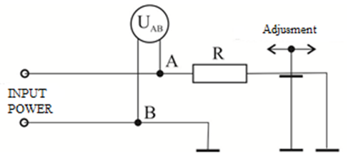
Figure 10
Load resistance is designed to provide an active load with a constant value for a certain frequency range. The resistance value is chosen to allow the wattmeter to be connected to a suitable power transmission line. In this way, the voltage value can be measured at any point on the transmission line before the switch-on point of the resistor by means of a voltage measuring probe. The measured voltage can be converted into power using the equation P = U2 / R.
The wattmeter scale is calibrated for direct power reading in watts. Thus, if the voltage meter has a linear scale, the power will be read from a scale plotted on a quadratic law.
The power dissipated by the load resistance of the wattmeter and the maximum value of the voltage that can be measured with the voltmeter limit the maximum power that can be measured with the wattmeter. The limitation in the value of the measured power caused by the load resistance is due to the maximum allowable temperature at which the load resistor can operate. As the value of the measured power increases, the temperature of the load resistor also increases. The voltmeter not only does not impose restrictions on the maximum allowable voltage, but also increases the minimum power value corresponding to the minimum voltage that can be measured with the required accuracy. For most wattmeters, this limit is of the order of 10% of the maximum reading of the indicator system at the lowest measuring range.
In general, wattmeters are calibrated to operate with a periodic signal, in which they measure the average value of its power. The average value of the input voltage is measured. If its amplitude changes over time (for example, in the case of an amplitude-modulated signal), the wattmeter will read the value of the power determined by the squares of the mean voltage. For signals other than periodic (Table 2), wattmeters calibrated on this basis will not give accurate readings. They should be recalculated for the corresponding waveform.
For example, if the amplitude modulated signal is measured with 100% modulation, the reported power value will be of the order of 2/3 of the true average power value.
To avoid these difficulties, a variant of the considered power measuring device is designed, whose voltmeter measures the amplitude value of the signal and not its average value. In this way, the read power value is proportional to the square of the voltage amplitude value, and this power is known as peak power. Therefore, the peak wattmeter measures the average power value for a given pulse or for a given peak (peak) of the signal energy.
Normally, the accuracy of the absorption power meter by measuring the voltage is ± 5% of the maximum reading of the indicator system. Part of the obtained discrepancy between the measured and the true value is due to the inaccuracy of the indicator device used as an output element. when working with a more accurate output device (for example, when using a digital voltmeter), higher accuracy can be obtained. Most of the error is due to the detector, which converts the high-frequency signal to DC, and some of the error is due to the relationship between the value of the source voltage and the voltage across the load.
1.3.2 Calorimetric wattmeters.
A) Simple calorimetric wattmeter.
The second type of absorption power meter is based on the direct determination of the electrical power dissipated on the load. As can be seen from Fig.11, and the determination of the power released on the load consists in determining the degree of heating of the resistor load on which the measured power is dissipated.
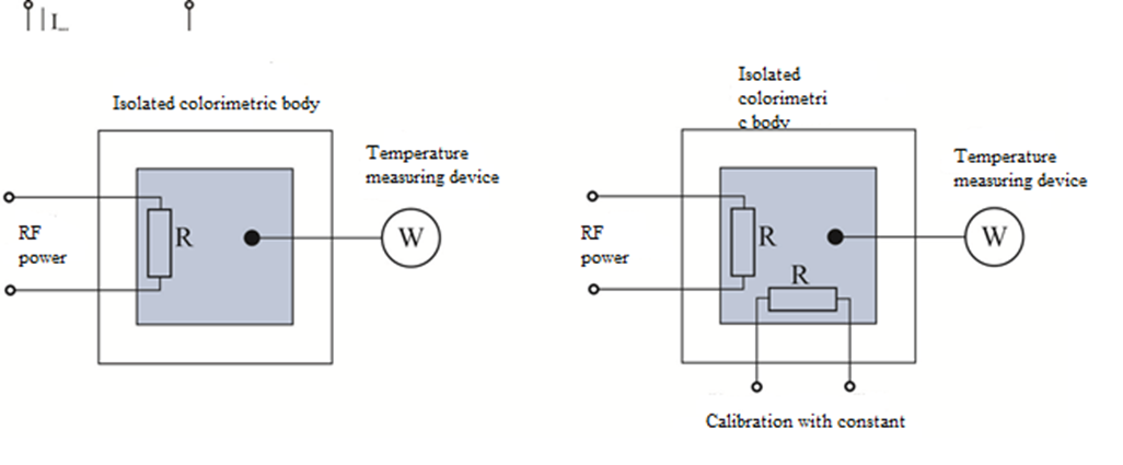
Fig.11
The main method for measuring electrical power is to dissipate in the form of heat on a resistive load and measure the value of the temperature rise. In principle, calorimetric power meters are based on the dissipation of a certain amount of energy in an isolated calorimetric body, where there is no possibility for external heat dissipation and measurement of the resulting temperature rise. The calorimetric electric power meter comprises a resistor which is connected to the electric power transmission line and the increase in temperature caused by the effect of the heat flux is measured. If the calorimetric body of a calorimeter is thermally isolated from the environment, the rate of temperature increase will be proportional to the power dissipated on the load.
The need to know the thermal mass of the calorimetric body, as well as the difficulties in achieving complete isolation from the environment, greatly limits the use of the basic type of calorimetric power meter. These problems are avoided by using a low-frequency DC or AC power source to calibrate the instrument, to measure the temperature at which a replacement calorimeter is obtained (Fig. 10 b).
Low-frequency DC or AC power requires the achievement of a specific temperature in the calorimeter, which can be measured using other instruments (voltmeter or electrodynamic wattmeter), which increases the accuracy of the measurement. The device of this type works by one of the following two methods:
First method. The value of the temperature obtained in the calorimetric body when applying the power of unknown value is taken into account. The power source of unknown value is then switched off and the calibrated power is increased until the calorimetric body reaches the same temperature again. The power from the unknown source is assumed to be equal to the power obtained from the calibrated power source.
The second method. Calibrated power is applied to the calorimetric body until a predetermined temperature value is obtained before the power is supplied from an unknown source. When the unknown power is applied, the calibrated power shall be reduced so that the temperature of the calorimetric body remains constant. Since the constant temperature is an indication that there is contact scattering of the total electric power in the calorimetric body, it can be assumed that the reduction of the calibrated power (it can be determined) is equal to the value of the unknown power.
In both cases, the assumption that equal amounts of DC power and power of unknown value in the high frequency range may lead to the same degree of increase in the temperature of the calorimetric body must be substantiated by appropriate calculations.
B) Flow calorimetric wattmeter.
This wattmeter contains: a load (liquid) for converting electrical energy into heat, a system for ensuring the circulation of the liquid and devices for measuring the temperature difference in the circulating liquid obtained by dissipation. electric power. The thermal mass of the liquid and the flow rate that passes through the power dissipation elements must be known. In addition, the increase in temperature difference caused by the supply of additional heat must be known.
1.3.3 Bolometric wattmeters.
One of the most commonly used devices for measuring high frequency power is a wattmeter using a bolometric bridge. The bolometer is a temperature dependent resistor. Its resistance changes with heating obtained from the dissipation of absorbed high-frequency power, this change the value of the resistor is measured with a bridge circuit. Almost all instruments of this type use specially designed elements that maintain a constant value of resistance during the measurement. The measurement is performed by two methods - by "substituting" the effect of high-frequency power on the bolometer or by direct current or low-frequency power.
Figure 12 shows the characteristics of bolometric elements. These elements are barreters and volumetric thermistors.
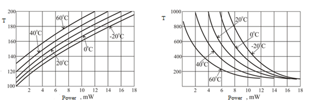
Figure 12
It can be seen from the figure that depending on the power supplied to the barreter or thermistor, their resistances change, in the case of a barretor the resistance increases with increasing power. With a thermistor, the resistance decreases. In both types of elements the characteristics are taken at the temperature parameter.